How to Use red led strip: Examples, Pinouts, and Specs
Introduction
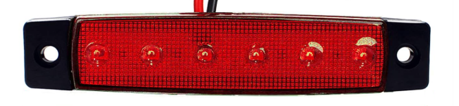
The Red LED Strip is a flexible circuit board with multiple red LEDs mounted on it. It is designed for decorative lighting, accent lighting, or illumination in various applications. Its flexibility and ease of use make it a popular choice for DIY projects, home decor, automotive lighting, and commercial displays. The strip can be cut to custom lengths and powered by a variety of sources, making it highly versatile.
Common applications include:
- Ambient lighting for homes, offices, or retail spaces
- Backlighting for TVs, monitors, or signage
- Automotive interior or exterior lighting
- Holiday or event decorations
- DIY electronics projects
Explore Projects Built with red led strip
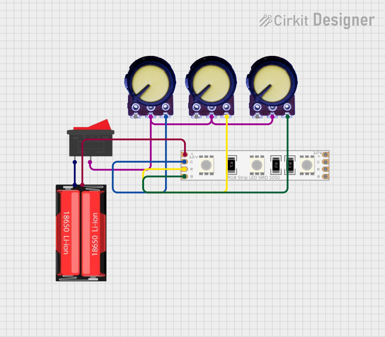
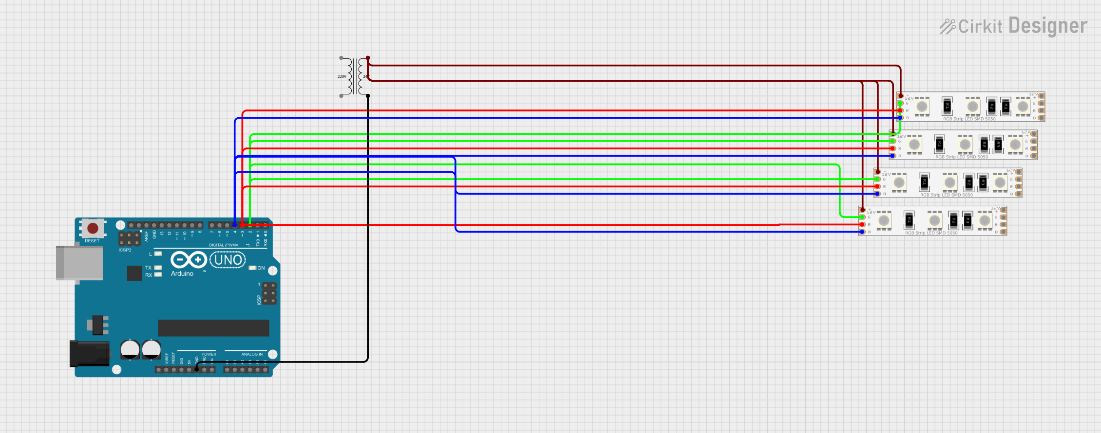
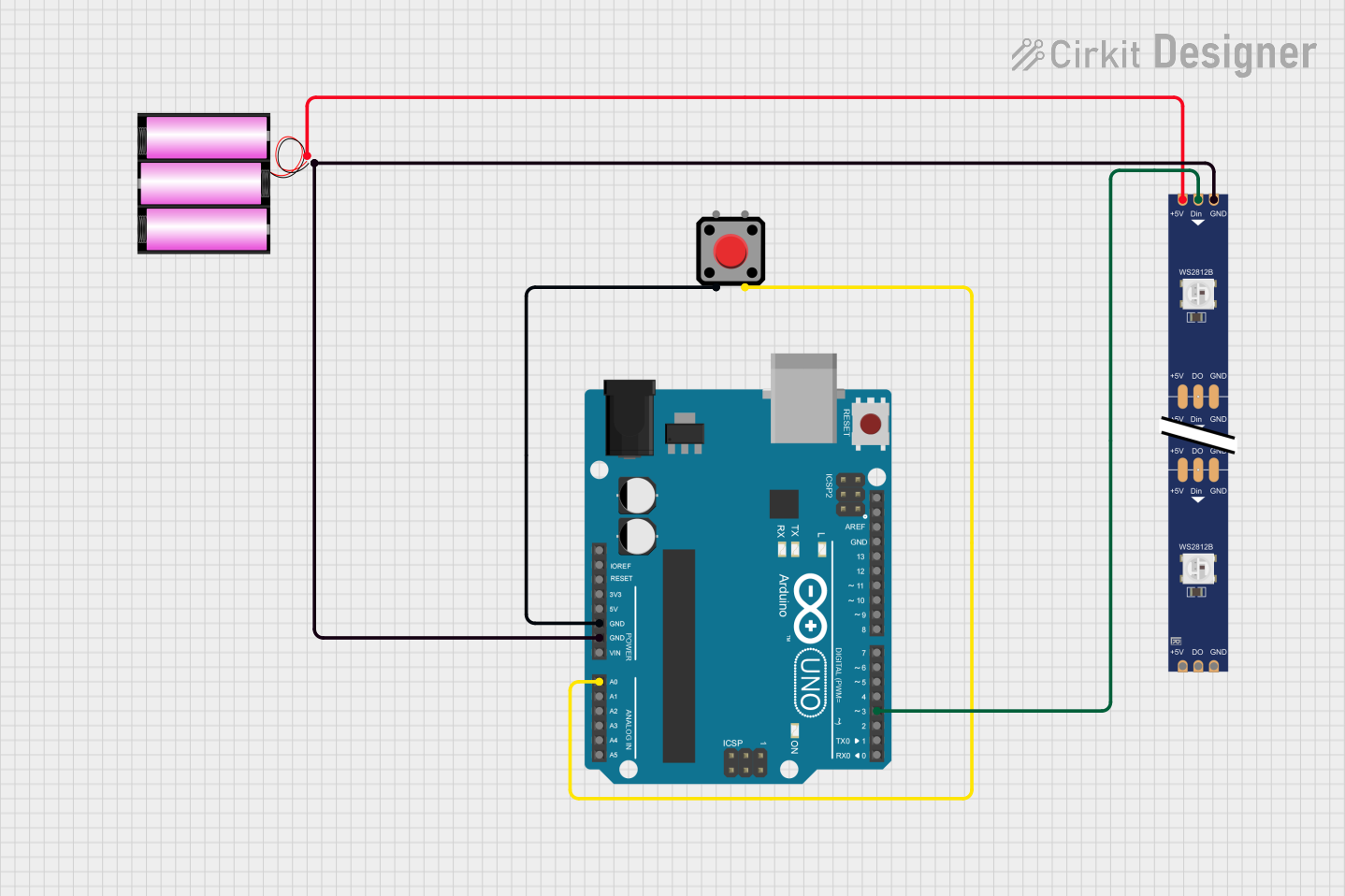
Explore Projects Built with red led strip
Technical Specifications
Below are the key technical details for a typical Red LED Strip. Specifications may vary slightly depending on the manufacturer.
| Parameter | Value |
|---|---|
| Operating Voltage | 12V DC (common) or 5V DC |
| Power Consumption | ~4.8W per meter (12V version) |
| LED Type | SMD 3528 or SMD 5050 |
| LED Color | Red |
| LED Density | 30, 60, or 120 LEDs per meter |
| Strip Length | Typically 5 meters (reel) |
| Cuttable Sections | Every 3 LEDs (12V version) |
| Waterproof Rating | IP20 (non-waterproof) or IP65/IP67 (waterproof) |
| Adhesive Backing | Yes (3M adhesive tape) |
Pin Configuration and Descriptions
The Red LED Strip typically has two pins for connection:
| Pin | Label | Description |
|---|---|---|
| 1 | +12V or +5V | Positive voltage input |
| 2 | GND | Ground connection |
Usage Instructions
Connecting the Red LED Strip
Power Supply Selection:
- Use a DC power supply that matches the operating voltage of the LED strip (e.g., 12V or 5V).
- Ensure the power supply can provide sufficient current for the length of the strip. For example, a 5-meter strip consuming 4.8W per meter at 12V requires a power supply rated for at least 2A.
Cutting the Strip:
- The strip can be cut at marked intervals (usually every 3 LEDs for 12V strips).
- Use sharp scissors to cut along the designated cut lines.
Connecting to Power:
- Connect the positive pin of the strip to the positive terminal of the power supply.
- Connect the ground pin of the strip to the ground terminal of the power supply.
Mounting:
- Peel off the protective layer from the adhesive backing and stick the strip to a clean, dry surface.
Using with an Arduino UNO
The Red LED Strip can be controlled using an Arduino UNO and a transistor or MOSFET to handle the current. Below is an example circuit and code to control the brightness of the strip using PWM.
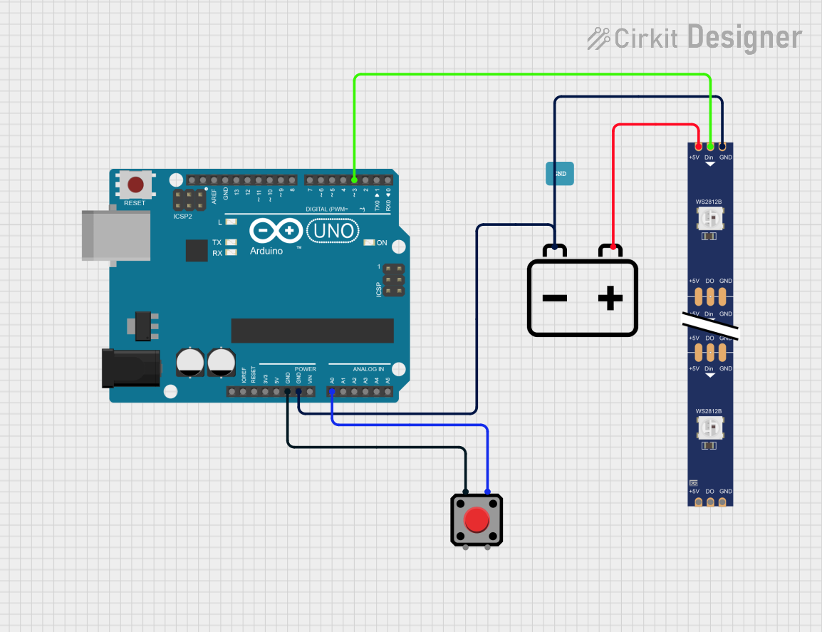
Circuit Diagram
- Connect the positive pin of the LED strip to the 12V power supply.
- Connect the ground pin of the LED strip to the drain of an N-channel MOSFET (e.g., IRF540N).
- Connect the source of the MOSFET to the ground of the power supply.
- Connect the gate of the MOSFET to a PWM-capable pin on the Arduino (e.g., Pin 9) through a 220-ohm resistor.
- Connect the ground of the Arduino to the ground of the power supply.
Arduino Code
// Red LED Strip Brightness Control
// This code uses PWM to adjust the brightness of a red LED strip.
// Connect the MOSFET gate to Pin 9 on the Arduino.

const int ledPin = 9; // PWM pin connected to the MOSFET gate

void setup() {
  pinMode(ledPin, OUTPUT); // Set the pin as an output
}

void loop() {
  // Gradually increase brightness
  for (int brightness = 0; brightness <= 255; brightness++) {
    analogWrite(ledPin, brightness); // Write PWM signal
    delay(10); // Small delay for smooth transition
  }

  // Gradually decrease brightness
  for (int brightness = 255; brightness >= 0; brightness--) {
    analogWrite(ledPin, brightness); // Write PWM signal
    delay(10); // Small delay for smooth transition
  }
}
Important Considerations
- Voltage Matching: Ensure the power supply voltage matches the LED strip's operating voltage.
- Heat Management: For long strips or high-density LEDs, consider using an aluminum channel for heat dissipation.
- Current Handling: Use appropriate wiring and connectors to handle the current drawn by the strip.
- Polarity: Always connect the strip with the correct polarity to avoid damage.
Troubleshooting and FAQs
Common Issues
LED Strip Does Not Light Up:
- Check the power supply connection and ensure it is turned on.
- Verify that the voltage matches the strip's requirements.
- Ensure the polarity of the connections is correct.
Only Part of the Strip Lights Up:
- Inspect the strip for physical damage or broken connections.
- Check if the strip was cut incorrectly or at the wrong location.
LEDs Flicker or Dim:
- Ensure the power supply can provide sufficient current.
- Check for loose or poor connections.
Strip Overheats:
- Verify that the strip is not drawing more current than specified.
- Use proper heat dissipation methods, such as aluminum channels.
FAQs
Q: Can I connect multiple strips together?
A: Yes, but ensure the power supply can handle the combined current. For long runs, consider injecting power at multiple points to prevent voltage drop.
Q: Can I use a 12V strip with a 5V power supply?
A: No, the strip will not function properly. Always use a power supply that matches the strip's voltage.
Q: How do I make the strip waterproof?
A: Use a waterproof version of the strip (IP65 or higher) or encase the strip in a silicone sleeve.
Q: Can I control the strip with a remote?
A: Yes, you can use an LED controller with a remote for easy control of brightness and effects.
By following this documentation, you can effectively use and troubleshoot your Red LED Strip for various applications.