How to Use Dumb Multiplexer: Examples, Pinouts, and Specs
Introduction
The Dumb Multiplexer by Lennart Herlaar is a straightforward electronic component designed to select one of several input signals and forward the selected input to a single output line. Unlike advanced multiplexers, this component does not include additional features such as buffering, signal amplification, or error correction. Its simplicity makes it ideal for basic signal routing applications where minimal overhead is required.
Explore Projects Built with Dumb Multiplexer


Explore Projects Built with Dumb Multiplexer
Common Applications and Use Cases
- Signal selection in digital circuits
- Data routing in microcontroller-based systems
- Simplified control of multiple sensors or devices
- Educational purposes for learning about multiplexing concepts
Technical Specifications
The Dumb Multiplexer is designed for basic signal routing and operates within the following parameters:
| Parameter | Value |
|---|---|
| Supply Voltage (Vcc) | 3.3V to 5V |
| Input Voltage Range | 0V to Vcc |
| Maximum Current | 10mA per channel |
| Number of Inputs | 4, 8, or 16 (depending on model) |
| Control Lines | 2, 3, or 4 (for 4, 8, or 16 inputs) |
| Output Impedance | ~100Ω |
| Operating Temperature | -40°C to 85°C |
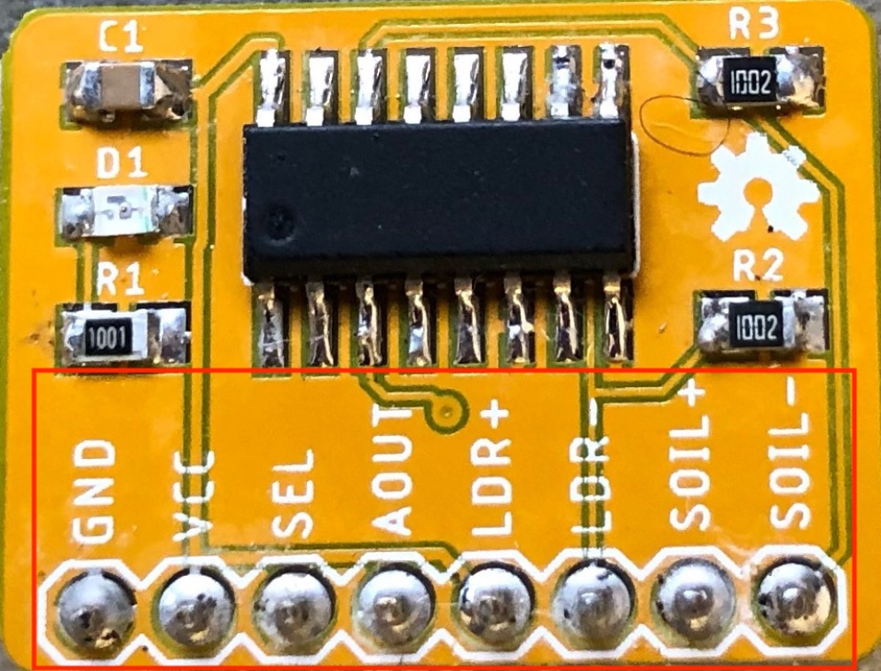
Pin Configuration and Descriptions
Below is the pinout for the 8-input Dumb Multiplexer model:
| Pin | Name | Description |
|---|---|---|
| 1 | Input 0 | First input signal |
| 2 | Input 1 | Second input signal |
| 3 | Input 2 | Third input signal |
| 4 | Input 3 | Fourth input signal |
| 5 | Input 4 | Fifth input signal |
| 6 | Input 5 | Sixth input signal |
| 7 | Input 6 | Seventh input signal |
| 8 | Input 7 | Eighth input signal |
| 9 | GND | Ground connection |
| 10 | Output | Selected input signal output |
| 11 | Select Line 0 | First control line for input selection |
| 12 | Select Line 1 | Second control line for input selection |
| 13 | Select Line 2 | Third control line for input selection (if needed) |
| 14 | Vcc | Power supply (3.3V to 5V) |
Usage Instructions
How to Use the Dumb Multiplexer in a Circuit
- Power the Multiplexer: Connect the Vcc pin to a 3.3V or 5V power source and the GND pin to ground.
- Connect Input Signals: Attach the signals you want to multiplex to the input pins (e.g., Input 0 to Input 7 for the 8-input model).
- Control Signal Selection: Use the select lines (e.g., Select Line 0, Select Line 1, etc.) to choose which input signal is forwarded to the output pin. The binary value on the select lines determines the active input.
- Read the Output: The selected input signal will appear on the output pin.
Important Considerations and Best Practices
- Signal Integrity: Since the Dumb Multiplexer does not include buffering, ensure that the input signals are within the specified voltage range and are not too noisy.
- Control Logic: Use a microcontroller or logic circuit to generate the appropriate binary signals for the select lines.
- Avoid Overloading: Do not exceed the maximum current rating of 10mA per channel to prevent damage to the component.
- Decoupling Capacitor: Place a small decoupling capacitor (e.g., 0.1µF) between Vcc and GND to stabilize the power supply.
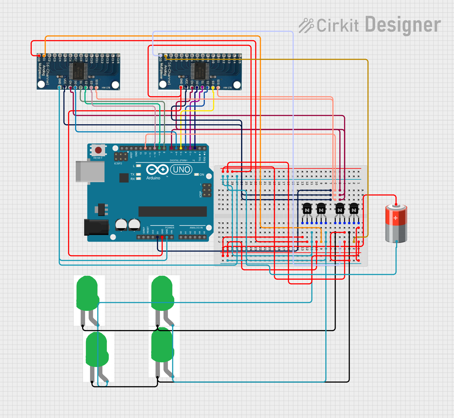
Example: Connecting to an Arduino UNO
Below is an example of how to use the Dumb Multiplexer with an Arduino UNO to select one of four input signals:
// Define select line pins connected to the Arduino
const int selectPin0 = 2; // Connect to Select Line 0
const int selectPin1 = 3; // Connect to Select Line 1

// Define the output pin of the multiplexer
const int muxOutput = A0; // Connect to the multiplexer output

void setup() {
  // Set select pins as outputs
  pinMode(selectPin0, OUTPUT);
  pinMode(selectPin1, OUTPUT);

  // Set up serial communication for debugging
  Serial.begin(9600);
}

void loop() {
  for (int i = 0; i < 4; i++) {
    // Set the select lines to choose the input
    digitalWrite(selectPin0, i & 0x01); // Least significant bit
    digitalWrite(selectPin1, (i >> 1) & 0x01); // Most significant bit

    // Read the selected input signal
    int signal = analogRead(muxOutput);

    // Print the signal value to the serial monitor
    Serial.print("Input ");
    Serial.print(i);
    Serial.print(": ");
    Serial.println(signal);

    delay(500); // Wait for 500ms before selecting the next input
  }
}
Troubleshooting and FAQs
Common Issues and Solutions
No Output Signal
- Cause: Incorrect wiring or no power supply.
- Solution: Double-check all connections, ensure Vcc and GND are properly connected, and verify the input signals.
Incorrect Input Selected
- Cause: Misconfigured select lines.
- Solution: Verify the binary values sent to the select lines match the desired input.
Signal Distortion
- Cause: High output impedance or noisy input signals.
- Solution: Use shorter wires, add a pull-down resistor on the output, or use a buffer circuit.
Component Overheating
- Cause: Exceeding the maximum current rating.
- Solution: Ensure the input and output signals do not exceed 10mA.
FAQs
Q: Can the Dumb Multiplexer handle analog signals?
A: Yes, the Dumb Multiplexer can route analog signals as long as they are within the specified voltage range (0V to Vcc).
Q: How many inputs can I use with this multiplexer?
A: The number of inputs depends on the model. Options include 4, 8, or 16 inputs.
Q: Does the multiplexer amplify the signal?
A: No, the Dumb Multiplexer does not include any amplification or buffering. It simply forwards the selected input signal to the output.
Q: Can I use this component with a 3.3V microcontroller?
A: Yes, the Dumb Multiplexer is compatible with both 3.3V and 5V systems. Ensure the input signals are within the appropriate voltage range.