Cirkit Designer Logo
Cirkit Designer
Your all-in-one circuit design IDE
Home / 
Component Documentation

How to Use loadcell: Examples, Pinouts, and Specs

Image of loadcell
Cirkit Designer LogoDesign with loadcell in Cirkit Designer

Introduction

A load cell, such as the AAA-003 manufactured by AAA, is a transducer that converts force or weight into an electrical signal. This signal is typically proportional to the applied force, enabling precise weight measurement. Load cells are widely used in applications such as digital weighing scales, industrial automation systems, material testing machines, and force measurement devices.

Explore Projects Built with loadcell

Use Cirkit Designer to design, explore, and prototype these projects online. Some projects support real-time simulation. Click "Open Project" to start designing instantly!
ESP8266-Based Smart Load Cell with Bluetooth and Battery Power
Image of IOT: A project utilizing loadcell in a practical application
This circuit is a wireless load measurement system using an ESP8266 NodeMCU microcontroller. It includes a load cell connected to an HX711 load cell amplifier, which sends data to the ESP8266. The system also features an HC-05 Bluetooth module for wireless communication, a red LED for status indication, and a buzzer for audible alerts, all powered by a battery case with two 18650 Li-ion batteries.
Cirkit Designer LogoOpen Project in Cirkit Designer
Arduino Nano-Based GPS and GSM Tracking System with Load Cell Integration
Image of load cell: A project utilizing loadcell in a practical application
This is a multi-functional circuit designed for location tracking, cellular communication, and weight measurement. It uses an Arduino Nano to interface with a GPS module, a GSM module, and a load cell with an HX711 amplifier, displaying data on an I2C LCD screen. Power is supplied by a Li-Ion battery through a buck converter, with a rocker switch for power control and a pushbutton for user input.
Cirkit Designer LogoOpen Project in Cirkit Designer
ESP8266 NodeMCU Controlled Weighing Scale with Bluetooth Connectivity
Image of IOT: A project utilizing loadcell in a practical application
This circuit features an ESP8266 NodeMCU microcontroller interfaced with an HX711 load cell amplifier, which is connected to a load cell for weight measurement. The NodeMCU also controls a red LED and a buzzer for output indications and communicates with an HC-05 Bluetooth module for wireless data transmission. The entire circuit is powered by a battery case, presumably containing two 18650 Li-ion batteries, providing power to the microcontroller, load cell amplifier, Bluetooth module, LED, and buzzer.
Cirkit Designer LogoOpen Project in Cirkit Designer
Solar-Powered Bottle-Weight Activated Phone Charging Station
Image of pr2 circuit diagram: A project utilizing loadcell in a practical application
This circuit is designed for a solar-powered charging station that uses a solar panel to charge a 12V battery through a solar charge controller. An Arduino UNO controls a relay to provide power from the battery to a USB power boost converter, allowing for phone charging when a load cell detects a weight above a certain threshold. The system status and charging activity are displayed on an LCD screen, and the load cell's signal is amplified by an HX711 amplifier for the Arduino to read the weight accurately.
Cirkit Designer LogoOpen Project in Cirkit Designer

Explore Projects Built with loadcell

Use Cirkit Designer to design, explore, and prototype these projects online. Some projects support real-time simulation. Click "Open Project" to start designing instantly!
Image of IOT: A project utilizing loadcell in a practical application
ESP8266-Based Smart Load Cell with Bluetooth and Battery Power
This circuit is a wireless load measurement system using an ESP8266 NodeMCU microcontroller. It includes a load cell connected to an HX711 load cell amplifier, which sends data to the ESP8266. The system also features an HC-05 Bluetooth module for wireless communication, a red LED for status indication, and a buzzer for audible alerts, all powered by a battery case with two 18650 Li-ion batteries.
Cirkit Designer LogoOpen Project in Cirkit Designer
Image of load cell: A project utilizing loadcell in a practical application
Arduino Nano-Based GPS and GSM Tracking System with Load Cell Integration
This is a multi-functional circuit designed for location tracking, cellular communication, and weight measurement. It uses an Arduino Nano to interface with a GPS module, a GSM module, and a load cell with an HX711 amplifier, displaying data on an I2C LCD screen. Power is supplied by a Li-Ion battery through a buck converter, with a rocker switch for power control and a pushbutton for user input.
Cirkit Designer LogoOpen Project in Cirkit Designer
Image of IOT: A project utilizing loadcell in a practical application
ESP8266 NodeMCU Controlled Weighing Scale with Bluetooth Connectivity
This circuit features an ESP8266 NodeMCU microcontroller interfaced with an HX711 load cell amplifier, which is connected to a load cell for weight measurement. The NodeMCU also controls a red LED and a buzzer for output indications and communicates with an HC-05 Bluetooth module for wireless data transmission. The entire circuit is powered by a battery case, presumably containing two 18650 Li-ion batteries, providing power to the microcontroller, load cell amplifier, Bluetooth module, LED, and buzzer.
Cirkit Designer LogoOpen Project in Cirkit Designer
Image of pr2 circuit diagram: A project utilizing loadcell in a practical application
Solar-Powered Bottle-Weight Activated Phone Charging Station
This circuit is designed for a solar-powered charging station that uses a solar panel to charge a 12V battery through a solar charge controller. An Arduino UNO controls a relay to provide power from the battery to a USB power boost converter, allowing for phone charging when a load cell detects a weight above a certain threshold. The system status and charging activity are displayed on an LCD screen, and the load cell's signal is amplified by an HX711 amplifier for the Arduino to read the weight accurately.
Cirkit Designer LogoOpen Project in Cirkit Designer

Common Applications:

  • Digital weighing scales
  • Industrial process control and automation
  • Material testing and tensile strength measurement
  • Force measurement in robotics and machinery
  • Load monitoring in structural engineering

Technical Specifications

The AAA-003 load cell is designed for high accuracy and reliability in weight measurement applications. Below are its key technical details:

Key Specifications:

Parameter Value
Manufacturer AAA
Part ID 003
Type Strain gauge-based load cell
Rated Load Capacity 5 kg (varies by model variant)
Output Sensitivity 1 mV/V
Excitation Voltage 5V to 12V DC
Operating Temperature -10°C to +40°C
Accuracy Class ±0.02% of full scale
Material Aluminum alloy
Overload Protection Up to 150% of rated capacity

Pin Configuration:

The AAA-003 load cell typically has four wires for electrical connections. The pinout is as follows:

Wire Color Function Description
Red Excitation (+) Positive voltage input for excitation
Black Excitation (-) Negative voltage input for excitation
Green Signal (+) Positive output signal
White Signal (-) Negative output signal

Usage Instructions

How to Use the Load Cell in a Circuit:

  1. Wiring the Load Cell:

    • Connect the red wire to the positive terminal of the excitation voltage (e.g., 5V).
    • Connect the black wire to the ground (GND) of the power supply.
    • Connect the green wire to the positive input of the signal amplifier or ADC (Analog-to-Digital Converter).
    • Connect the white wire to the negative input of the signal amplifier or ADC.
  2. Amplifying the Signal:

    • The output signal of the load cell is typically in the millivolt range and requires amplification.
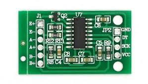
    • Use a load cell amplifier module, such as the HX711, to amplify the signal and convert it to a digital format.
  3. Connecting to a Microcontroller:

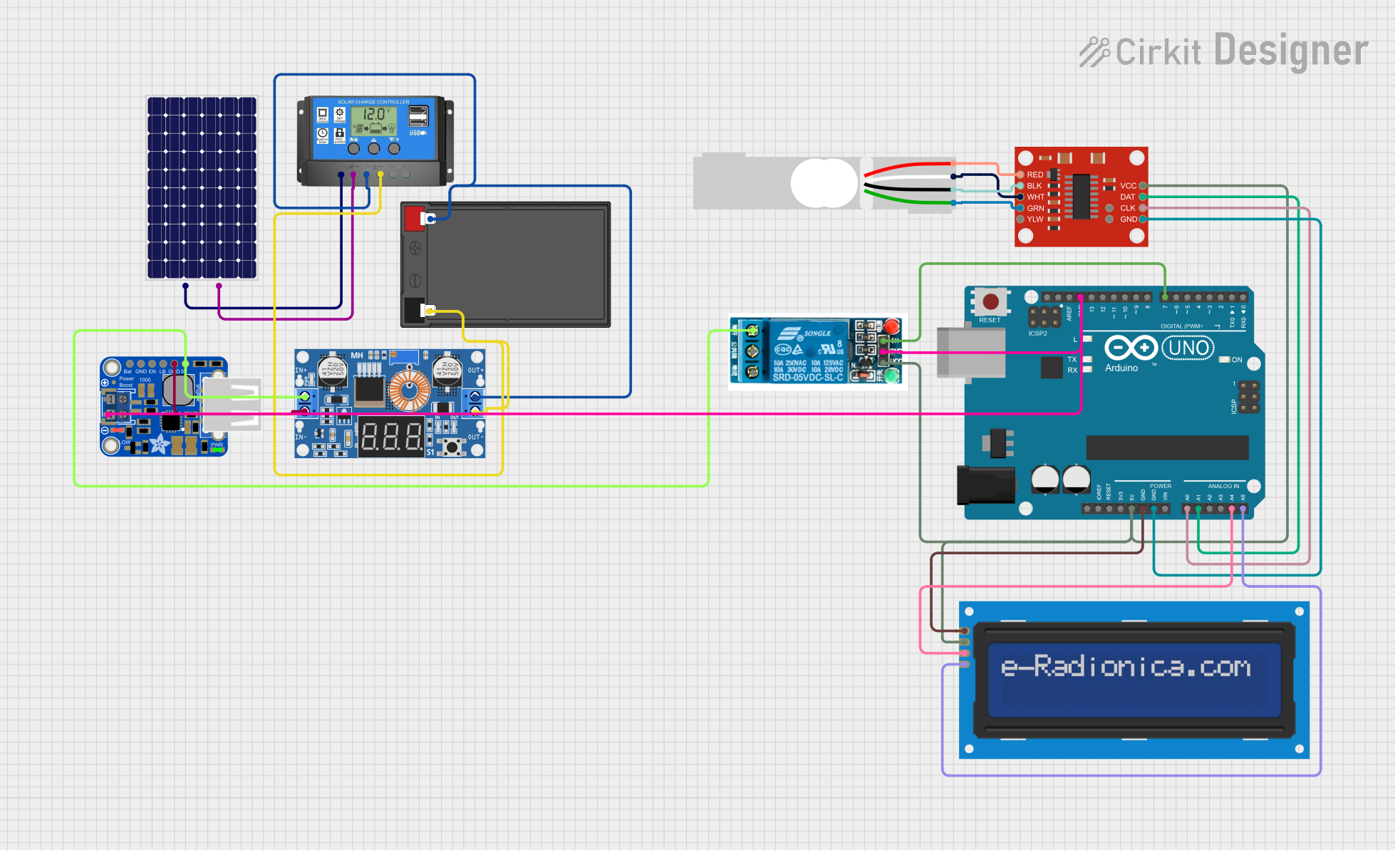
    • The amplified signal can be interfaced with a microcontroller (e.g., Arduino UNO) for further processing and display.

Example: Connecting the Load Cell to an Arduino UNO

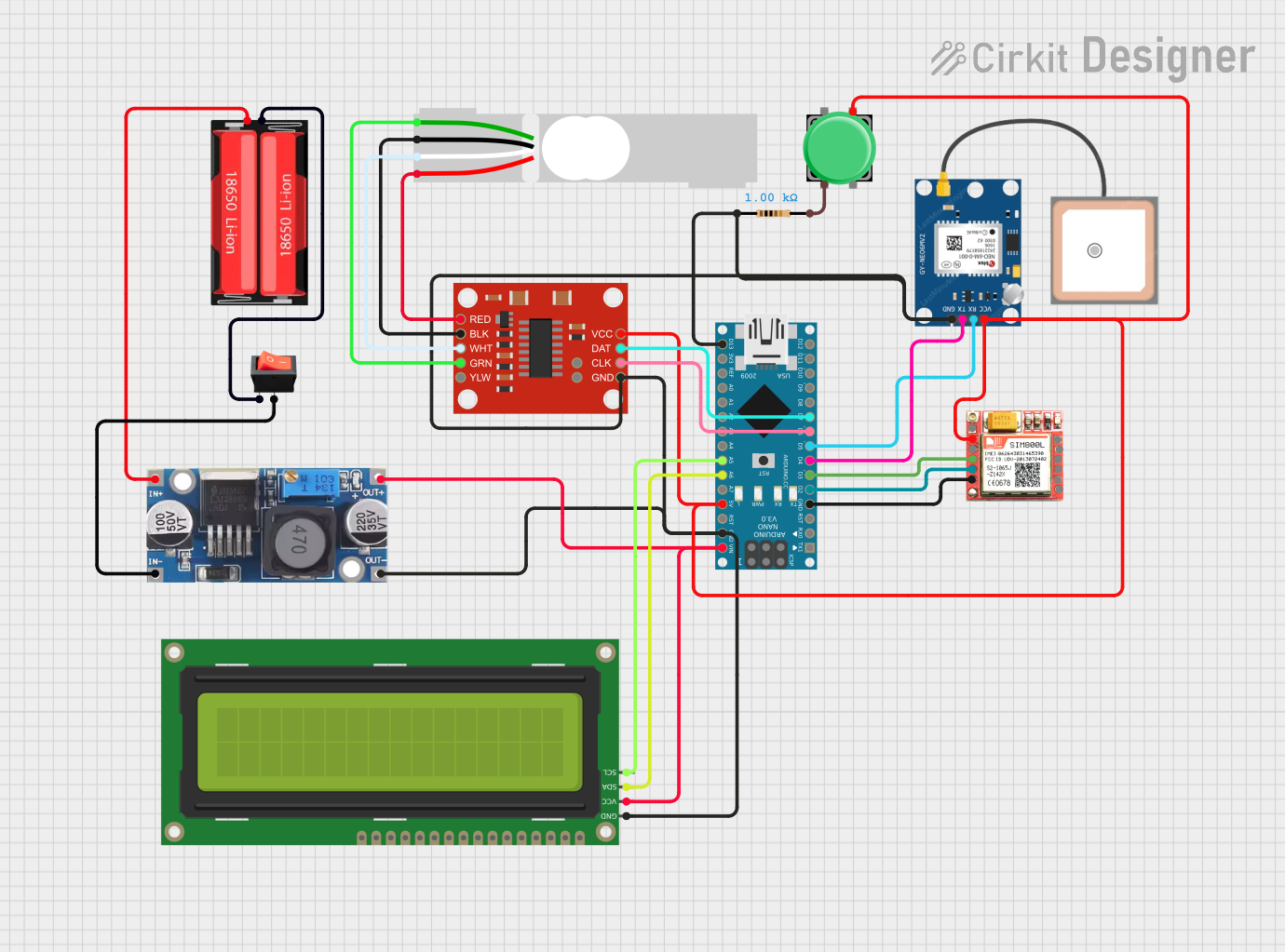
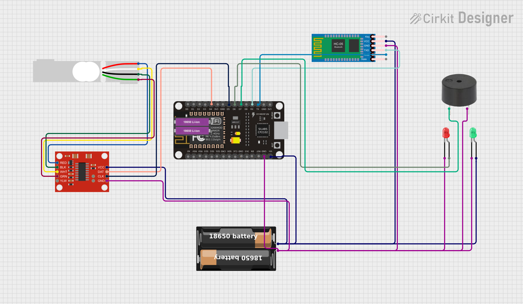
Below is an example of how to connect the AAA-003 load cell to an Arduino UNO using the HX711 module:

Circuit Diagram:

  • Connect the load cell wires to the HX711 module as follows:
    • Red wire to E+ (Excitation +)
    • Black wire to E- (Excitation -)
    • Green wire to A+ (Signal +)
    • White wire to A- (Signal -)
  • Connect the HX711 module to the Arduino UNO:
    • VCC to 5V
    • GND to GND
    • DT (Data) to pin 3
    • SCK (Clock) to pin 2

Arduino Code:

#include "HX711.h"

// Define HX711 pins
#define DT 3  // Data pin connected to Arduino pin 3
#define SCK 2 // Clock pin connected to Arduino pin 2

HX711 scale;

void setup() {
  Serial.begin(9600); // Initialize serial communication
  scale.begin(DT, SCK); // Initialize HX711 with defined pins
  Serial.println("Load Cell Initialized");
}

void loop() {
  if (scale.is_ready()) {
    // Read weight value from the load cell
    long weight = scale.get_units(10); // Average of 10 readings
    Serial.print("Weight: ");
    Serial.print(weight);
    Serial.println(" grams");
  } else {
    Serial.println("HX711 not ready");
  }
  delay(500); // Wait for 500ms before the next reading
}

Important Considerations:

  • Calibration: Always calibrate the load cell before use to ensure accurate measurements.
  • Overload Protection: Avoid exceeding the rated load capacity to prevent damage.
  • Temperature Effects: Ensure the operating environment is within the specified temperature range to maintain accuracy.
  • Noise Reduction: Use shielded cables and proper grounding to minimize electrical noise.

Troubleshooting and FAQs

Common Issues and Solutions:

  1. No Output Signal:

    • Cause: Incorrect wiring or loose connections.
    • Solution: Verify all connections and ensure the wires are securely connected to the amplifier module.
  2. Inconsistent Readings:

    • Cause: Electrical noise or unstable power supply.
    • Solution: Use a stable power source and shielded cables to reduce noise.
  3. Output Signal Saturation:

    • Cause: Overloading the load cell beyond its rated capacity.
    • Solution: Ensure the applied load is within the specified range.
  4. HX711 Not Responding:

    • Cause: Incorrect pin connections or faulty module.
    • Solution: Double-check the wiring and replace the HX711 module if necessary.

FAQs:

Q1: Can I use the AAA-003 load cell with a 3.3V microcontroller?
A1: Yes, but ensure the excitation voltage is within the specified range (5V to 12V). Use a level shifter if necessary for signal compatibility.

Q2: How do I calibrate the load cell?
A2: Use a known weight and adjust the calibration factor in your code until the output matches the actual weight.

Q3: Can the load cell measure both compression and tension?
A3: Yes, the AAA-003 load cell can measure both compression and tension forces.

Q4: What is the maximum cable length for the load cell?
A4: The maximum cable length depends on the operating environment and signal quality. For best results, use shielded cables and keep the length under 5 meters.

By following this documentation, you can effectively integrate the AAA-003 load cell into your projects for accurate and reliable weight measurement.