How to Use Electronics-Salon 2 DPDT : Examples, Pinouts, and Specs
Introduction
The Electronics-Salon 2 DPDT switch is a versatile and robust component that plays a crucial role in electronic circuits. A Double-Pole, Double-Throw (DPDT) switch can control two different circuits within a single switch mechanism, allowing for more complex switching operations. This switch is commonly used in applications such as reversing the direction of motors, switching between different audio signals, or as part of relay and toggle operations.
Explore Projects Built with Electronics-Salon 2 DPDT


Explore Projects Built with Electronics-Salon 2 DPDT
Common Applications and Use Cases
- Motor direction control
- Audio equipment signal routing
- Relay systems
- Toggle operations between two circuits
- Switching power between different circuit paths
Technical Specifications
Key Technical Details
- Switch Type: DPDT (Double-Pole, Double-Throw)
- Maximum Voltage: XX VAC/VDC (specify the voltage rating)
- Maximum Current: XX A (specify the current rating)
- Contact Resistance: XX mΩ (specify the resistance)
- Insulation Resistance: XX MΩ at XX VDC (specify the insulation resistance)
- Dielectric Strength: XX VAC for 1 minute (specify the dielectric strength)
- Mechanical Life: XX cycles (specify the mechanical life)
- Operating Temperature Range: XX to XX°C (specify the temperature range)
Pin Configuration and Descriptions
| Pin Number | Description |
|---|---|
| 1 | Pole 1, Input/Output |
| 2 | Pole 1, Throw 1 |
| 3 | Pole 1, Throw 2 |
| 4 | Pole 2, Input/Output |
| 5 | Pole 2, Throw 1 |
| 6 | Pole 2, Throw 2 |
Usage Instructions
How to Use the Component in a Circuit
- Identify the Poles and Throws: Determine which pins correspond to the poles and throws of the switch.
- Circuit Integration: Connect the poles to the common points in your circuit that you wish to switch between.
- Throw Connections: Connect the throws to the separate circuits or components that you want to toggle or switch.
- Testing: Before applying power, ensure all connections are secure and correct.
Important Considerations and Best Practices
- Voltage and Current Ratings: Do not exceed the maximum voltage and current ratings to prevent damage.
- Switching Loads: When switching inductive loads, consider using a snubber circuit to protect the switch contacts from voltage spikes.
- Mounting: Secure the switch firmly to your project or enclosure to prevent movement during operation.
- Debouncing: If using the switch to input signals to a digital circuit, consider implementing debouncing techniques to ensure clean signal transitions.
Troubleshooting and FAQs
Common Issues
- Intermittent Connections: Check for loose wiring or solder joints.
- Switch Does Not Operate: Verify that the voltage and current are within the specified range.
- Unexpected Circuit Behavior: Ensure that the switch is wired correctly according to the pin configuration.
Solutions and Tips for Troubleshooting
- Secure Connections: Re-solder or tighten connections if necessary.
- Check Ratings: Use a multimeter to verify that the operating conditions are within the switch's specifications.
- Review Wiring: Double-check the wiring against the pin configuration to ensure accuracy.
FAQs
Q: Can I use this switch with an Arduino UNO? A: Yes, the switch can be used to control circuits connected to an Arduino UNO, provided the voltage and current ratings are within the Arduino's limits.
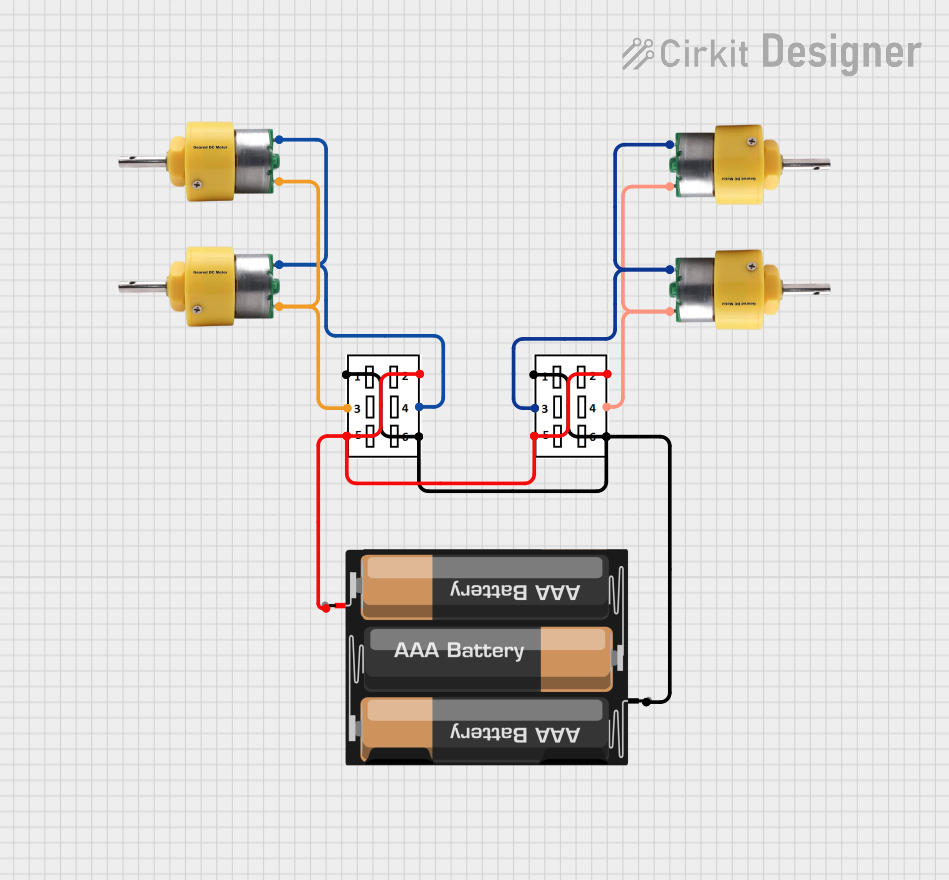
Q: How do I reverse the direction of a DC motor with this switch? A: Connect the motor between the throws of one pole, and supply voltage to the common pin. Flipping the switch will reverse the polarity and thus the motor direction.
Q: Is debouncing necessary for this switch? A: If the switch is used for digital signal input, debouncing is recommended to prevent multiple signal changes from mechanical vibrations.
Example Code for Arduino UNO
// Example code to read the state of the DPDT switch connected to an Arduino UNO

const int switchPin1 = 2; // Connect to Pole 1
const int switchPin2 = 3; // Connect to Pole 2

void setup() {
  pinMode(switchPin1, INPUT_PULLUP); // Set the switch pin as input with internal pull-up
  pinMode(switchPin2, INPUT_PULLUP);
  Serial.begin(9600);
}

void loop() {
  int stateSwitch1 = digitalRead(switchPin1); // Read the state of the switch
  int stateSwitch2 = digitalRead(switchPin2);

  // Output the state of the switch to the Serial Monitor
  Serial.print("Switch 1 State: ");
  Serial.print(stateSwitch1);
  Serial.print(" | Switch 2 State: ");
  Serial.println(stateSwitch2);

  delay(100); // Debounce delay
}
Note: The above code assumes that the DPDT switch is connected in such a way that when the switch is in one position, the connection is made between the pole and throw 1, and when in the other position, the connection is made between the pole and throw 2. Adjust the pin numbers and logic according to your specific wiring.