How to Use raspi schem: Examples, Pinouts, and Specs
Introduction
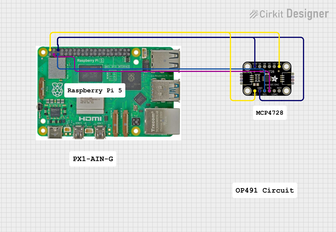
The RasPi Schem is a schematic representation of a Raspberry Pi, providing a detailed overview of its connections, pinouts, and interfacing options. This tool is essential for understanding how to connect various electronic components to the Raspberry Pi, ensuring proper functionality and avoiding damage to the board or peripherals.
Common applications of the RasPi Schem include:
- Designing circuits and projects involving the Raspberry Pi.
- Learning and teaching Raspberry Pi GPIO pin configurations.
- Debugging and troubleshooting Raspberry Pi-based systems.
- Planning and documenting hardware setups for IoT, robotics, and automation projects.
Explore Projects Built with raspi schem
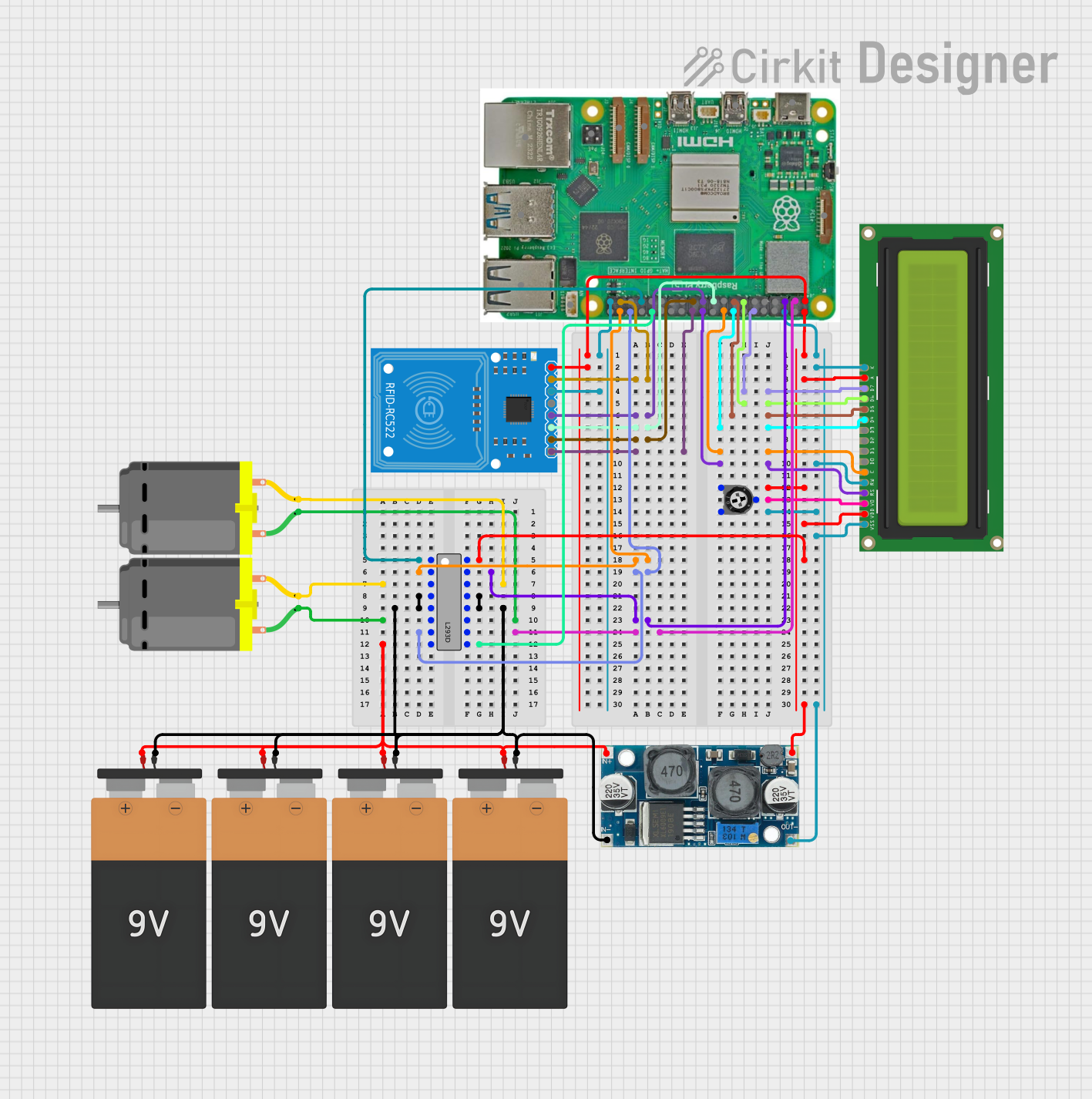
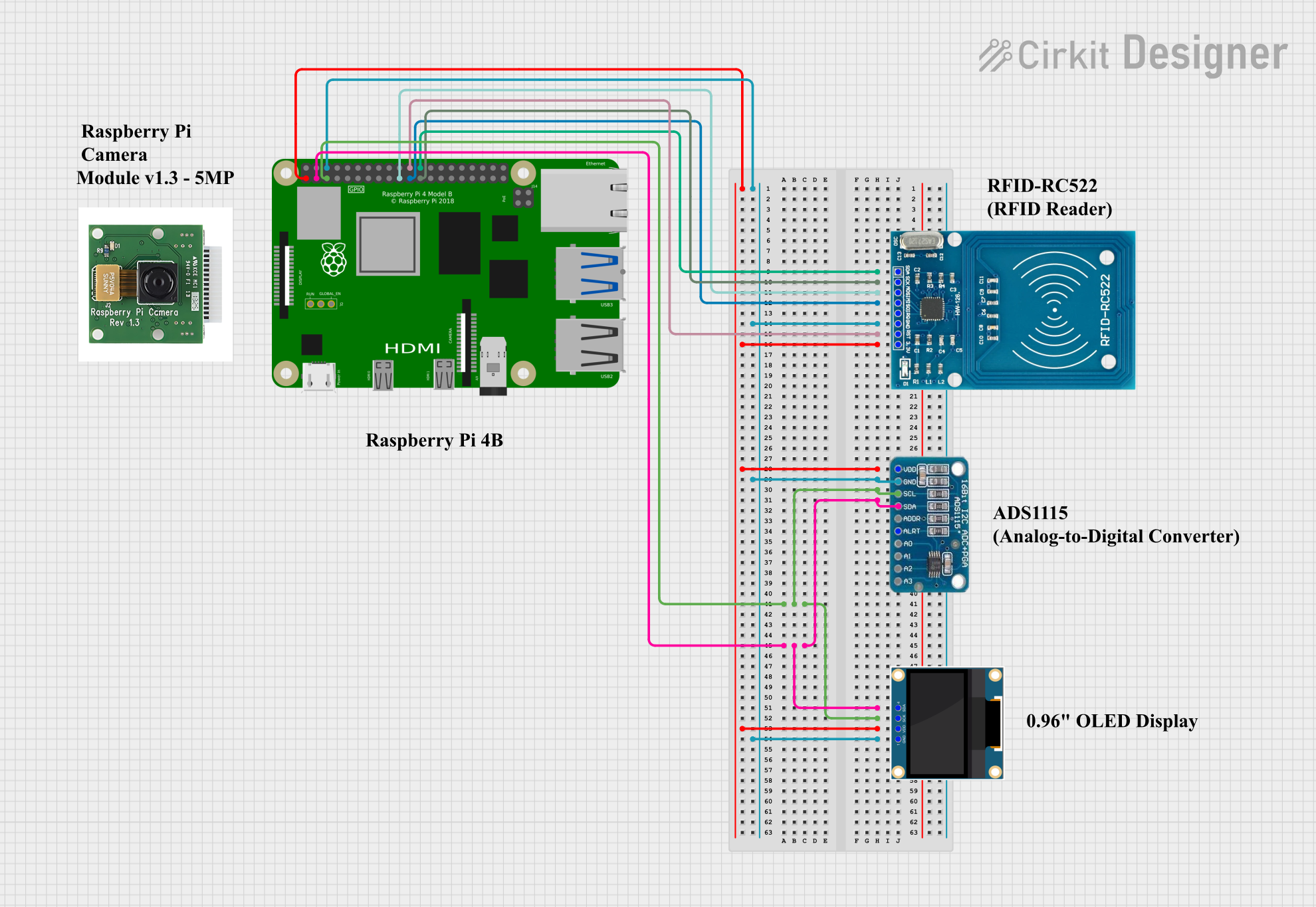
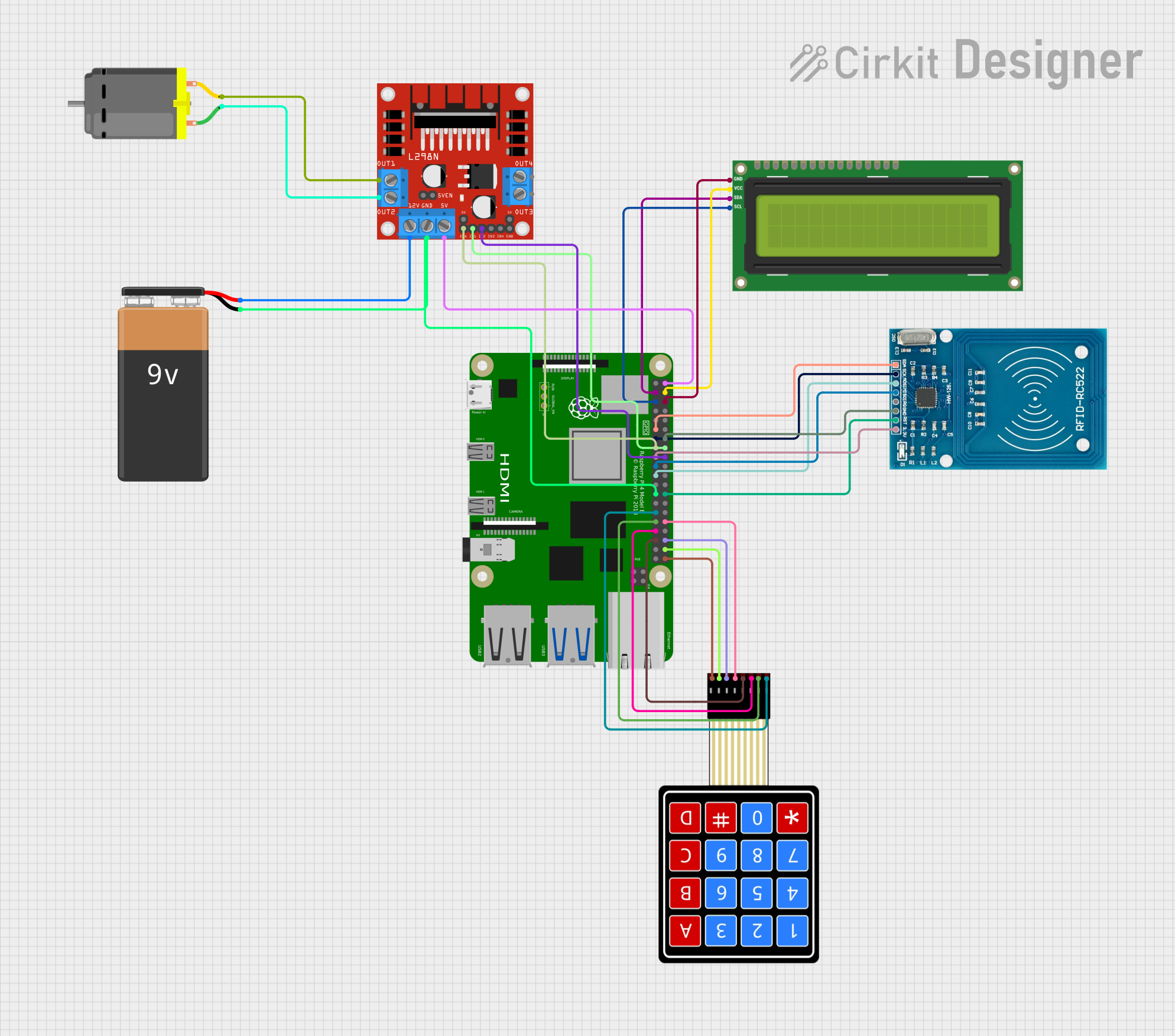
Explore Projects Built with raspi schem
Technical Specifications
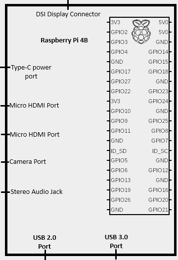
The RasPi Schem provides a visual and tabular representation of the Raspberry Pi's GPIO pins and other key connections. Below are the technical details:
GPIO Pin Configuration
The Raspberry Pi GPIO header consists of 40 pins, arranged in a 2x20 grid. The table below outlines the pin configuration:
| Pin Number | Pin Name | Functionality | Voltage Level |
|---|---|---|---|
| 1 | 3.3V Power | Power supply | 3.3V |
| 2 | 5V Power | Power supply | 5V |
| 3 | GPIO2 (SDA1) | I2C Data | 3.3V |
| 4 | 5V Power | Power supply | 5V |
| 5 | GPIO3 (SCL1) | I2C Clock | 3.3V |
| 6 | Ground | Ground | 0V |
| 7 | GPIO4 | General Purpose I/O | 3.3V |
| 8 | GPIO14 (TXD) | UART Transmit | 3.3V |
| 9 | Ground | Ground | 0V |
| 10 | GPIO15 (RXD) | UART Receive | 3.3V |
| ... | ... | ... | ... |
| 39 | Ground | Ground | 0V |
| 40 | GPIO21 | General Purpose I/O | 3.3V |
Note: The full pinout includes additional GPIO pins, SPI, I2C, UART, and power connections. Refer to the official Raspberry Pi documentation for a complete pinout.
Supported Interfaces
- I2C: For connecting sensors and peripherals like temperature sensors and OLED displays.
- SPI: For high-speed communication with devices like ADCs and displays.
- UART: For serial communication with other microcontrollers or PCs.
- PWM: For controlling servos, motors, and LEDs.
Usage Instructions
How to Use the RasPi Schem
- Understand the Pinout: Familiarize yourself with the GPIO pin configuration using the schematic.
- Plan Connections: Identify the pins required for your project (e.g., power, ground, data lines).
- Connect Components: Use jumper wires or a breadboard to connect components to the Raspberry Pi.
- Verify Connections: Double-check all connections to ensure they match the schematic and avoid short circuits.
Important Considerations
- Voltage Levels: The GPIO pins operate at 3.3V. Connecting 5V directly to a GPIO pin can damage the Raspberry Pi.
- Current Limits: Each GPIO pin can source/sink a maximum of 16mA, with a total limit of 50mA across all pins.
- Pull-Up/Down Resistors: Some GPIO pins have internal pull-up or pull-down resistors. Configure them in software if needed.
- Static Electricity: Handle the Raspberry Pi with care to avoid static discharge, which can damage the board.
Example: Blinking an LED with an Arduino UNO
The following example demonstrates how to use the RasPi Schem to connect an LED to GPIO17 (Pin 11) and control it using Python.
Circuit Setup
- Connect the LED's positive leg (anode) to GPIO17 (Pin 11).
- Connect the LED's negative leg (cathode) to a 330-ohm resistor.
- Connect the other end of the resistor to Ground (Pin 6).
Python Code
Import the GPIO library and time module
import RPi.GPIO as GPIO import time
Set the GPIO mode to BCM (Broadcom pin numbering)
GPIO.setmode(GPIO.BCM)
Define the GPIO pin for the LED
LED_PIN = 17
Set up the LED pin as an output
GPIO.setup(LED_PIN, GPIO.OUT)
try: while True: GPIO.output(LED_PIN, GPIO.HIGH) # Turn the LED on time.sleep(1) # Wait for 1 second GPIO.output(LED_PIN, GPIO.LOW) # Turn the LED off time.sleep(1) # Wait for 1 second except KeyboardInterrupt: # Clean up GPIO settings on exit GPIO.cleanup()
> **Note:** Ensure the Raspberry Pi is powered off while making connections. Power it on only after verifying the circuit.
Troubleshooting and FAQs
Common Issues
GPIO Pin Not Responding:
- Cause: Incorrect pin numbering or configuration.
- Solution: Verify the pin numbering (BCM vs. BOARD) and ensure the pin is set up correctly in the code.
Component Not Working:
- Cause: Loose connections or incorrect wiring.
- Solution: Check all connections against the RasPi Schem and ensure components are securely connected.
Raspberry Pi Not Booting:
- Cause: Short circuit or incorrect power supply.
- Solution: Disconnect all components and check for shorts. Use a 5V, 2.5A power supply.
Overheating:
- Cause: Excessive current draw or poor ventilation.
- Solution: Reduce the load on GPIO pins and ensure proper airflow around the Raspberry Pi.
FAQs
Q: Can I connect 5V components directly to GPIO pins?
A: No, the GPIO pins operate at 3.3V. Use a level shifter or voltage divider for 5V components.Q: How do I identify the pin numbering system?
A: The RasPi Schem uses BCM (Broadcom) numbering. You can also refer to the physical pin layout (BOARD numbering).Q: What is the maximum current the Raspberry Pi can supply?
A: The 3.3V and 5V pins can supply limited current. For high-power devices, use an external power source.
By following this documentation, you can effectively use the RasPi Schem to design and implement Raspberry Pi-based projects with confidence.