How to Use DCDC Boost Converter: Examples, Pinouts, and Specs
Introduction
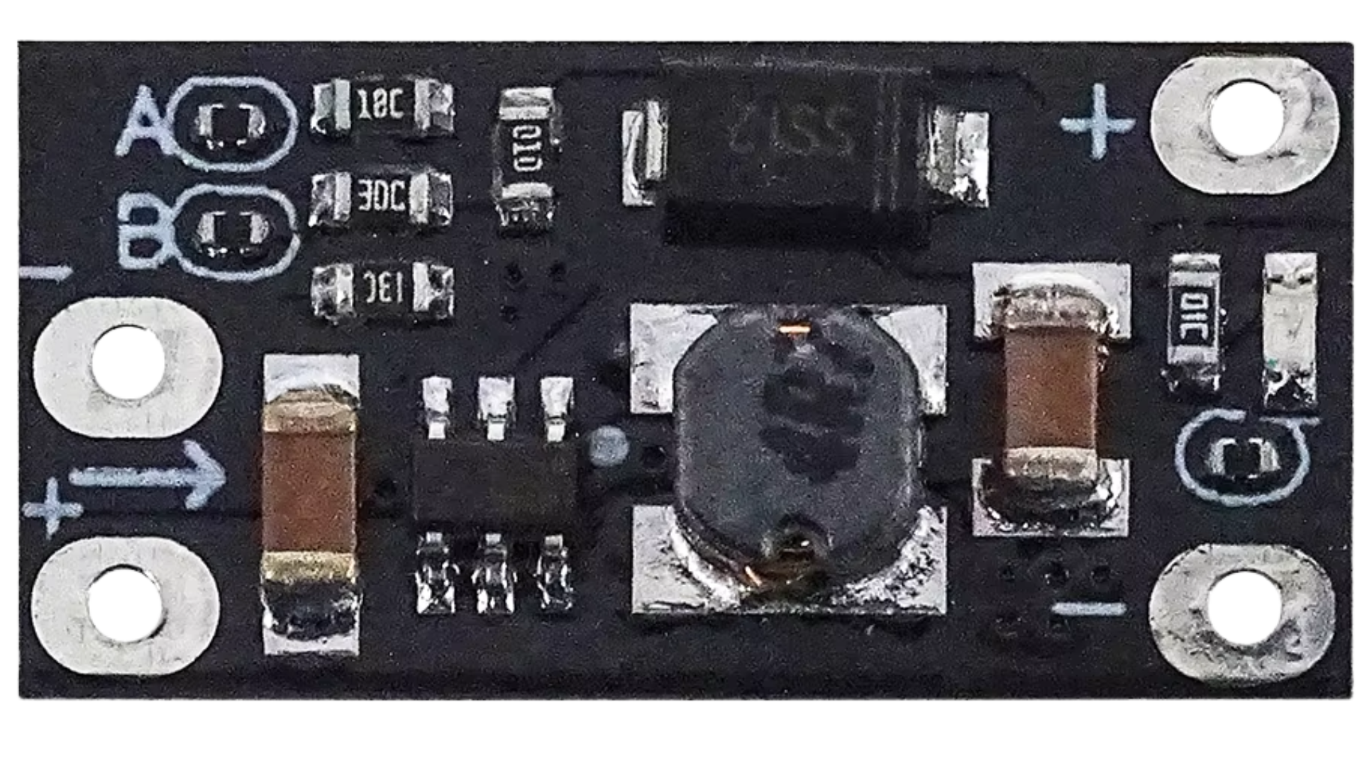
A DC-DC boost converter is a power converter that steps up (increases) the input voltage to a higher output voltage while maintaining the same polarity. It achieves this by using inductors, capacitors, and switching elements to store and transfer energy efficiently.
Explore Projects Built with DCDC Boost Converter


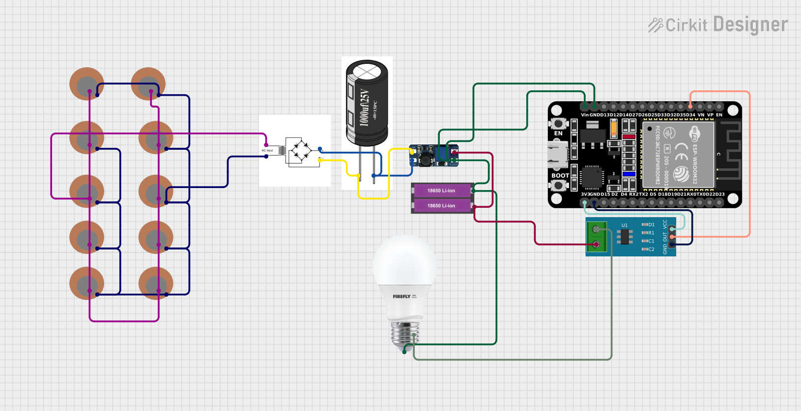
Explore Projects Built with DCDC Boost Converter
Common Applications and Use Cases
- Powering high-voltage devices from low-voltage batteries (e.g., LED strips, motor drivers)
- Solar power systems to step up panel voltage
- Portable electronics requiring higher voltage than the battery provides
- Automotive applications, such as powering 12V devices from a 5V USB source
Technical Specifications
Below are the general technical specifications for a typical DC-DC boost converter. Note that specific models may vary, so always refer to the datasheet of the exact module you are using.
| Parameter | Value |
|---|---|
| Input Voltage Range | 3V to 32V |
| Output Voltage Range | 5V to 35V (adjustable via potentiometer) |
| Maximum Output Current | 2A to 5A (depending on the model) |
| Efficiency | Up to 95% (depending on input/output ratio) |
| Switching Frequency | 150 kHz to 1 MHz |
| Operating Temperature | -40°C to +85°C |
Pin Configuration and Descriptions
| Pin Name | Description |
|---|---|
| VIN | Positive input voltage terminal |
| GND | Ground terminal (common for input and output) |
| VOUT | Positive output voltage terminal |
| ADJ (optional) | Adjustment pin for setting output voltage (if available) |
Usage Instructions
How to Use the Component in a Circuit
Connect the Input Voltage:
- Connect the positive terminal of your power source to the
VINpin. - Connect the negative terminal of your power source to the
GNDpin.
- Connect the positive terminal of your power source to the
Connect the Output Load:
- Connect the positive terminal of your load to the
VOUTpin. - Connect the negative terminal of your load to the
GNDpin.
- Connect the positive terminal of your load to the
Adjust the Output Voltage (if applicable):
- Use the onboard potentiometer (if available) to set the desired output voltage.
- Measure the output voltage using a multimeter while adjusting the potentiometer.
Power On:
- Turn on the input power source. The boost converter will step up the input voltage to the configured output voltage.
Important Considerations and Best Practices
- Input Voltage Range: Ensure the input voltage is within the specified range of the boost converter.
- Output Voltage Adjustment: Always adjust the output voltage without a load connected to avoid damaging the load.
- Heat Dissipation: For high current applications, ensure proper heat dissipation using heatsinks or active cooling.
- Capacitor Selection: Use appropriate input and output capacitors to reduce voltage ripple and improve stability.
- Polarity Protection: Double-check the polarity of the input and output connections to avoid damage.
Example: Using a DC-DC Boost Converter with Arduino UNO
Below is an example of using a DC-DC boost converter to power a 12V LED strip from a 5V Arduino UNO power source.
Circuit Connections
- Connect the Arduino's 5V pin to the
VINpin of the boost converter. - Connect the Arduino's GND pin to the
GNDpin of the boost converter. - Connect the
VOUTpin of the boost converter to the positive terminal of the LED strip. - Connect the negative terminal of the LED strip to the
GNDpin of the boost converter.
Arduino Code Example
The following code demonstrates controlling the LED strip using a PWM signal from the Arduino:
// Define the PWM pin connected to the LED strip
const int pwmPin = 9;

void setup() {
  // Set the PWM pin as an output
  pinMode(pwmPin, OUTPUT);
}

void loop() {
  // Gradually increase brightness
  for (int brightness = 0; brightness <= 255; brightness++) {
    analogWrite(pwmPin, brightness); // Write PWM signal to control brightness
    delay(10); // Small delay for smooth transition
  }

  // Gradually decrease brightness
  for (int brightness = 255; brightness >= 0; brightness--) {
    analogWrite(pwmPin, brightness); // Write PWM signal to control brightness
    delay(10); // Small delay for smooth transition
  }
}
Troubleshooting and FAQs
Common Issues and Solutions
No Output Voltage:
- Cause: Incorrect input polarity or loose connections.
- Solution: Verify the input polarity and ensure all connections are secure.
Output Voltage Not Adjustable:
- Cause: Faulty potentiometer or incorrect adjustment procedure.
- Solution: Check the potentiometer for damage and adjust it slowly while monitoring the output voltage.
Excessive Heat:
- Cause: Overloading the converter or insufficient cooling.
- Solution: Reduce the load current or add a heatsink to the converter.
High Voltage Ripple:
- Cause: Insufficient input/output capacitors.
- Solution: Add low-ESR capacitors to the input and output terminals.
FAQs
Q: Can I use a DC-DC boost converter to power sensitive electronics?
A: Yes, but ensure the output voltage is stable and within the tolerance range of your device. Adding capacitors can help reduce voltage ripple.
Q: What happens if I exceed the maximum input voltage?
A: Exceeding the input voltage can damage the boost converter. Always stay within the specified range.
Q: Can I use the boost converter in reverse to step down voltage?
A: No, a boost converter is designed only to step up voltage. Use a buck converter for stepping down voltage.
Q: How do I calculate the efficiency of the boost converter?
A: Efficiency (%) = (Output Power / Input Power) × 100. Measure the input and output voltage and current to calculate power.