
How to Use PWM Relay: Examples, Pinouts, and Specs
 Design with PWM Relay in Cirkit Designer
Introduction
A PWM (Pulse Width Modulation) relay is an electromechanical switch designed to control the power delivered to a load using PWM signals. By varying the duty cycle of the PWM signal, the relay enables precise control over devices such as motors, lights, and other electronic loads. This makes it an efficient solution for applications requiring variable speed, brightness, or power regulation.
Explore Projects Built with PWM Relay
 Open Project in Cirkit Designer
 Open Project in Cirkit Designer
 Open Project in Cirkit Designer
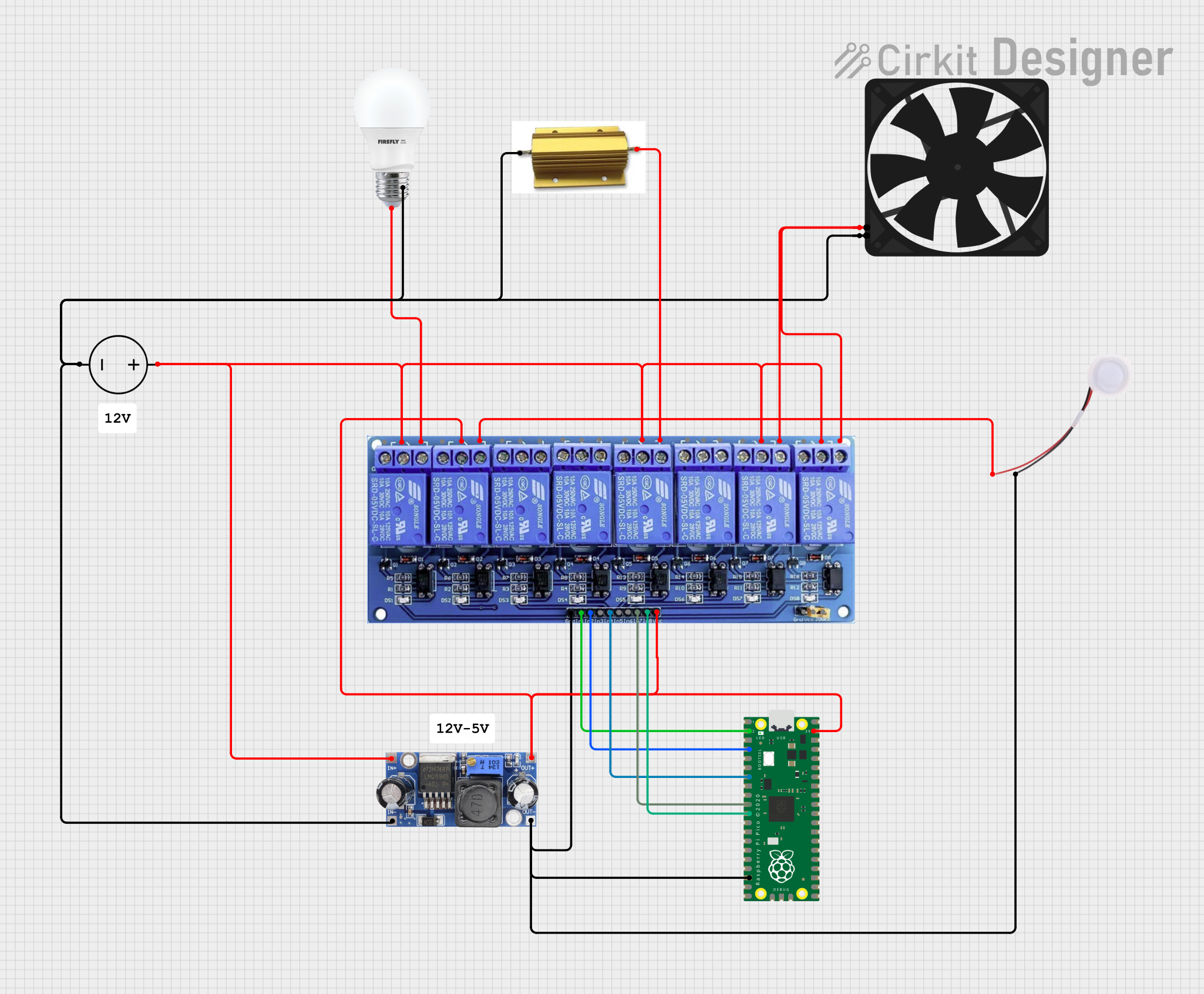 Open Project in Cirkit Designer
Explore Projects Built with PWM Relay
Open Project in Cirkit DesignerOpen Project in Cirkit DesignerOpen Project in Cirkit DesignerOpen Project in Cirkit DesignerCommon Applications
- Motor speed control in robotics and industrial systems
- LED brightness adjustment in lighting systems
- Heating element power regulation
- Fan speed control in HVAC systems
- Battery charging systems with controlled power delivery
Technical Specifications
Key Technical Details
| Parameter | Value |
|---|---|
| Operating Voltage | 5V, 12V, or 24V (model-dependent) |
| Control Signal Voltage | 3.3V to 5V (compatible with PWM) |
| Maximum Load Current | 10A |
| PWM Frequency Range | 100 Hz to 10 kHz |
| Duty Cycle Range | 0% to 100% |
| Relay Type | SPDT (Single Pole Double Throw) |
| Isolation | Optocoupler-based isolation |
| Operating Temperature | -20°C to 70°C |
Pin Configuration and Descriptions
| Pin Name | Description |
|---|---|
| VCC | Power supply input for the relay module (5V, 12V, or 24V depending on model) |
| GND | Ground connection |
| PWM_IN | Input pin for the PWM signal (3.3V to 5V logic level) |
| NO (Normally Open) | Normally open terminal of the relay; connects to the load when activated |
| NC (Normally Closed) | Normally closed terminal of the relay; disconnects when activated |
| COM | Common terminal for the relay switch |
Usage Instructions
How to Use the PWM Relay in a Circuit
- Power the Relay Module: Connect the VCC pin to the appropriate power supply (e.g., 5V, 12V, or 24V) and the GND pin to the ground.
- Connect the Load:
- For devices that should be powered when the relay is activated, connect the load between the NO (Normally Open) terminal and COM (Common) terminal.
- For devices that should be powered when the relay is deactivated, connect the load between the NC (Normally Closed) terminal and COM terminal.
- Provide a PWM Signal: Connect the PWM_IN pin to a microcontroller or PWM signal generator. Ensure the signal voltage is within the 3.3V to 5V range.
- Adjust the Duty Cycle: Use the PWM signal to control the relay's switching behavior. A higher duty cycle increases the power delivered to the load.
Important Considerations
- Isolation: The relay module typically includes optocoupler isolation to protect the control circuit from high voltages. Ensure proper isolation is maintained in your design.
- PWM Frequency: Select a PWM frequency within the supported range (100 Hz to 10 kHz) for optimal performance.
- Load Ratings: Do not exceed the maximum load current (10A) to avoid damaging the relay.
- Debouncing: If the relay is used for rapid switching, ensure the PWM signal is stable to prevent relay chatter.
Example: Using a PWM Relay with Arduino UNO
Below is an example of controlling a PWM relay to adjust the brightness of an LED:
// Define the PWM pin connected to the relay
const int pwmPin = 9; // Pin 9 on Arduino UNO supports PWM output

void setup() {
  pinMode(pwmPin, OUTPUT); // Set the PWM pin as an output
}

void loop() {
  // Gradually increase brightness
  for (int dutyCycle = 0; dutyCycle <= 255; dutyCycle++) {
    analogWrite(pwmPin, dutyCycle); // Write PWM signal to the relay
    delay(10); // Wait 10ms for smooth transition
  }

  // Gradually decrease brightness
  for (int dutyCycle = 255; dutyCycle >= 0; dutyCycle--) {
    analogWrite(pwmPin, dutyCycle); // Write PWM signal to the relay
    delay(10); // Wait 10ms for smooth transition
  }
}
Notes:
- The
analogWrite()function generates a PWM signal on the specified pin. - Adjust the delay value to control the speed of brightness transitions.
Troubleshooting and FAQs
Common Issues and Solutions
Relay Not Switching:
- Cause: Insufficient PWM signal voltage.
- Solution: Ensure the PWM_IN pin receives a signal within the 3.3V to 5V range.
Load Not Receiving Power:
- Cause: Incorrect wiring of the load to the relay terminals.
- Solution: Verify the load is connected to the correct terminals (NO or NC) based on the desired behavior.
Relay Chatter or Noise:
- Cause: Unstable or noisy PWM signal.
- Solution: Use a stable PWM source and ensure proper grounding.
Overheating:
- Cause: Exceeding the maximum load current.
- Solution: Ensure the load current does not exceed 10A. Use a heatsink or cooling if necessary.
FAQs
Q1: Can I use the PWM relay with a 3.3V microcontroller?
A1: Yes, the PWM_IN pin is compatible with 3.3V logic levels. Ensure the relay module's VCC matches the required operating voltage.
Q2: What happens if I use a PWM frequency outside the specified range?
A2: Using a frequency outside the 100 Hz to 10 kHz range may result in erratic relay behavior or reduced performance.
Q3: Can the relay handle AC loads?
A3: Yes, the relay can handle both AC and DC loads, provided the voltage and current ratings are not exceeded.
Q4: Is the relay suitable for high-speed switching?
A4: No, mechanical relays are not ideal for high-speed switching due to wear and tear. For high-speed applications, consider using solid-state relays (SSRs).