How to Use Mini servo : Examples, Pinouts, and Specs
Introduction
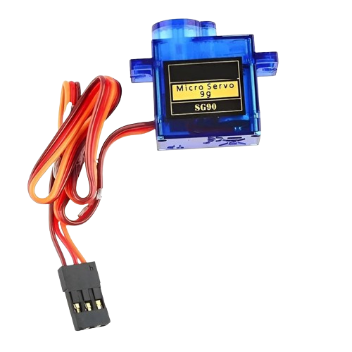
The Mini Servo is a compact motor capable of precise angular rotation, making it ideal for applications requiring controlled movement. It is widely used in robotics, remote-controlled devices, and automation systems. The servo operates by receiving a Pulse Width Modulation (PWM) signal, which determines the angle of rotation. Its small size and ease of use make it a popular choice for hobbyists and professionals alike.
Explore Projects Built with Mini servo


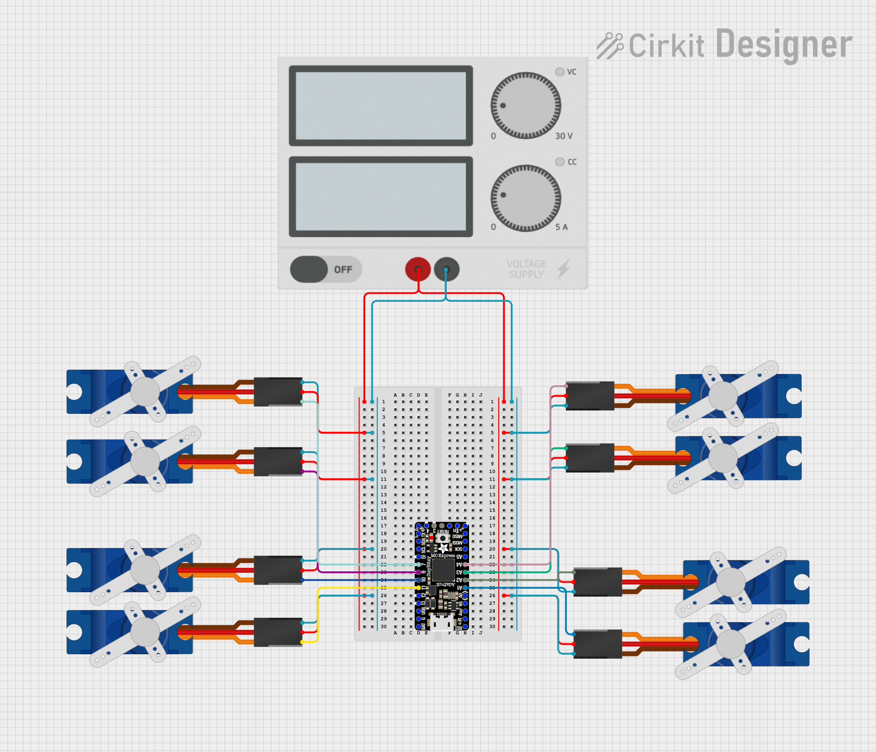
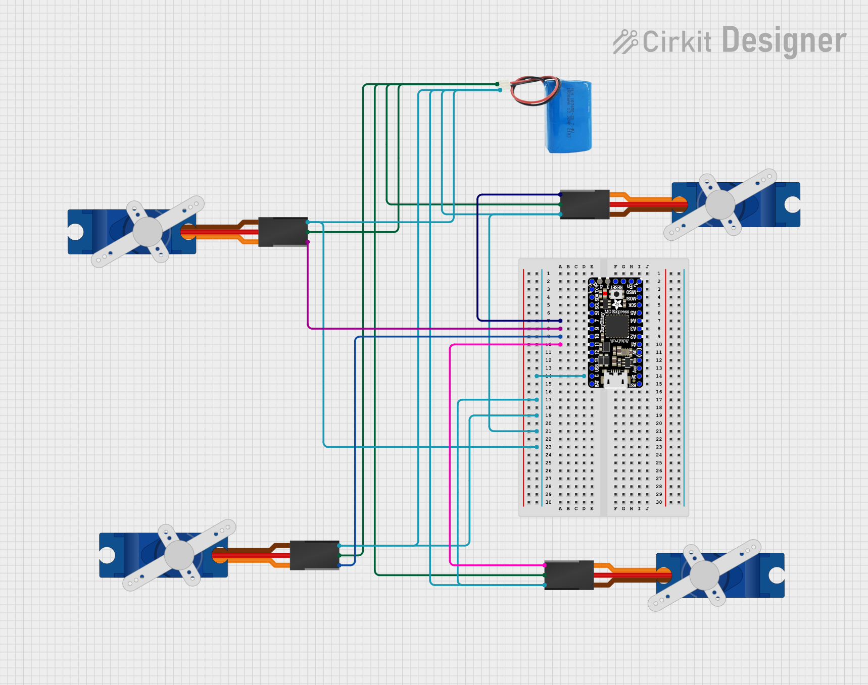
Explore Projects Built with Mini servo
Common Applications:
- Robotic arms and grippers
- Remote-controlled cars, boats, and planes
- Automated systems and mechanisms
- Educational projects and prototyping
Technical Specifications
Below are the key technical details of a typical Mini Servo:
| Parameter | Value |
|---|---|
| Operating Voltage | 4.8V to 6.0V |
| Stall Torque | ~1.8 kg·cm (at 4.8V) |
| Operating Speed | ~0.12 sec/60° (at 4.8V) |
| Control Signal | PWM (Pulse Width Modulation) |
| Angle of Rotation | 0° to 180° |
| Dimensions | ~22.2 x 11.8 x 31 mm |
| Weight | ~9 grams |
Pin Configuration:
The Mini Servo typically has three wires for connection:
| Pin Name | Wire Color | Description |
|---|---|---|
| VCC | Red | Power supply (4.8V to 6.0V) |
| GND | Black/Brown | Ground connection |
| Signal | Orange/White | PWM signal input for angle control |
Usage Instructions
How to Use the Mini Servo in a Circuit:
- Power Connection: Connect the red wire (VCC) to a 5V power source and the black/brown wire (GND) to the ground.
- Signal Connection: Connect the orange/white wire (Signal) to a PWM-capable pin on your microcontroller (e.g., Arduino).
- PWM Signal: Use a PWM signal to control the servo's angle. A typical PWM signal has a frequency of 50 Hz, with a pulse width of 1 ms to 2 ms corresponding to 0° to 180°.
Important Considerations:
- Power Supply: Ensure the power supply can provide sufficient current (at least 1A) to avoid voltage drops.
- Avoid Overloading: Do not exceed the torque rating to prevent damage to the servo.
- Signal Stability: Use a stable PWM signal to avoid erratic movements.
- Mechanical Limits: Do not force the servo beyond its physical rotation limits (0° to 180°).
Example: Connecting a Mini Servo to an Arduino UNO
Below is an example Arduino code to control a Mini Servo:
#include <Servo.h> // Include the Servo library

Servo myServo; // Create a Servo object

void setup() {
  myServo.attach(9); // Attach the servo to pin 9
}

void loop() {
  myServo.write(0); // Move servo to 0 degrees
  delay(1000); // Wait for 1 second

  myServo.write(90); // Move servo to 90 degrees
  delay(1000); // Wait for 1 second

  myServo.write(180); // Move servo to 180 degrees
  delay(1000); // Wait for 1 second
}
Code Explanation:
- The
Servolibrary simplifies servo control. - The
attach()function links the servo to a specific pin. - The
write()function sets the servo angle (0° to 180°). - Delays allow the servo to reach the desired position before the next command.
Troubleshooting and FAQs
Common Issues:
Servo Not Moving:
- Cause: Incorrect wiring or insufficient power supply.
- Solution: Double-check connections and ensure the power source provides adequate current.
Erratic Movements:
- Cause: Unstable PWM signal or electrical noise.
- Solution: Use a decoupling capacitor near the servo's power pins and ensure a clean PWM signal.
Overheating:
- Cause: Prolonged stalling or overloading.
- Solution: Avoid exceeding the torque rating and ensure the servo is not physically obstructed.
Limited Rotation:
- Cause: Servo is a standard type with a 180° limit.
- Solution: Use a continuous rotation servo if 360° movement is required.
FAQs:
Q: Can I power the Mini Servo directly from the Arduino?
A: While possible, it is not recommended as the Arduino's 5V pin may not supply enough current. Use an external power source.Q: How do I control multiple servos?
A: Use multiple PWM-capable pins or a servo driver module for better control.Q: Can the Mini Servo rotate beyond 180°?
A: No, standard Mini Servos are limited to 0° to 180°. For continuous rotation, use a modified or specialized servo.
By following this documentation, you can effectively integrate and troubleshoot the Mini Servo in your projects.