How to Use HW484 v0.2: Examples, Pinouts, and Specs
Introduction
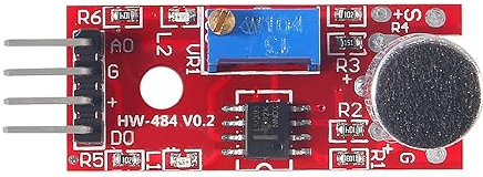
The HW484 v0.2 is a versatile hardware platform designed for a wide range of electronic projects. It integrates a microcontroller, multiple input/output (I/O) interfaces, and supports various sensors and actuators, making it an ideal choice for prototyping, educational purposes, and IoT applications. Its compact design and robust functionality allow users to build and test projects efficiently.
Explore Projects Built with HW484 v0.2


Explore Projects Built with HW484 v0.2
Common Applications and Use Cases
- IoT (Internet of Things) devices
- Home automation systems
- Robotics and motor control
- Environmental monitoring with sensors
- Educational projects and prototyping
Technical Specifications
The HW484 v0.2 is built to provide flexibility and ease of use. Below are its key technical details:
General Specifications
| Parameter | Value |
|---|---|
| Microcontroller | 32-bit ARM Cortex-M4 |
| Operating Voltage | 3.3V |
| Input Voltage Range | 5V (via USB) or 7-12V (VIN) |
| Digital I/O Pins | 14 (6 PWM capable) |
| Analog Input Pins | 6 |
| Communication Interfaces | UART, I2C, SPI |
| Clock Speed | 72 MHz |
| Flash Memory | 256 KB |
| SRAM | 64 KB |
| Dimensions | 50mm x 25mm |
Pin Configuration and Descriptions
The HW484 v0.2 features a standard pinout for easy integration into projects. Below is the pin configuration:
| Pin Number | Pin Name | Description |
|---|---|---|
| 1 | VIN | External power input (7-12V) |
| 2 | GND | Ground |
| 3 | 3.3V | Regulated 3.3V output |
| 4 | A0 | Analog input 0 |
| 5 | A1 | Analog input 1 |
| 6 | A2 | Analog input 2 |
| 7 | A3 | Analog input 3 |
| 8 | A4 | Analog input 4 / I2C SDA |
| 9 | A5 | Analog input 5 / I2C SCL |
| 10 | D0 | Digital I/O 0 / UART RX |
| 11 | D1 | Digital I/O 1 / UART TX |
| 12 | D2 | Digital I/O 2 |
| 13 | D3 | Digital I/O 3 (PWM capable) |
| 14 | D4 | Digital I/O 4 |
| 15 | D5 | Digital I/O 5 (PWM capable) |
| 16 | D6 | Digital I/O 6 (PWM capable) |
| 17 | D7 | Digital I/O 7 |
| 18 | D8 | Digital I/O 8 |
| 19 | D9 | Digital I/O 9 (PWM capable) |
| 20 | D10 | Digital I/O 10 (PWM capable) |
| 21 | D11 | Digital I/O 11 / SPI MOSI |
| 22 | D12 | Digital I/O 12 / SPI MISO |
| 23 | D13 | Digital I/O 13 / SPI SCK |
Usage Instructions
The HW484 v0.2 is designed for ease of use in a variety of projects. Follow the steps below to get started:
Basic Setup
Powering the Board:
- Connect a 5V USB power source to the micro-USB port, or supply 7-12V to the VIN pin.
- Ensure the GND pin is connected to the ground of your circuit.
Connecting Sensors and Actuators:
- Use the analog pins (A0-A5) for sensors that output analog signals.
- Use the digital pins (D0-D13) for digital sensors, actuators, or communication.
Programming the Board:
- The HW484 v0.2 is compatible with the Arduino IDE. Select the appropriate board and port in the IDE settings.
- Write your code and upload it to the board via the USB connection.
Example: Reading an Analog Sensor
Below is an example of how to read an analog sensor connected to pin A0 and display the value in the Arduino Serial Monitor:
// Example code for HW484 v0.2: Reading an analog sensor

void setup() {
  Serial.begin(9600); // Initialize serial communication at 9600 baud
}

void loop() {
  int sensorValue = analogRead(A0); // Read the value from the sensor on pin A0
  Serial.print("Sensor Value: ");   // Print a label for the sensor value
  Serial.println(sensorValue);     // Print the sensor value to the Serial Monitor
  delay(500);                      // Wait for 500ms before reading again
}
Important Considerations
- Voltage Levels: Ensure that all connected components operate at 3.3V logic levels to avoid damaging the board.
- Pin Current Limits: Do not exceed 20mA per I/O pin or 200mA total for all pins.
- Heat Management: If using the board at high loads, ensure proper ventilation to prevent overheating.
Troubleshooting and FAQs
Common Issues and Solutions
Board Not Detected by Computer:
- Ensure the USB cable is functional and properly connected.
- Check that the correct board and port are selected in the Arduino IDE.
Program Not Uploading:
- Verify that no other application is using the COM port.
- Press the reset button on the board before uploading.
Incorrect Sensor Readings:
- Confirm that the sensor is connected to the correct pin.
- Check for loose connections or incorrect wiring.
Board Overheating:
- Reduce the load on the I/O pins.
- Ensure the input voltage does not exceed the recommended range.
FAQs
Q: Can I use 5V sensors with the HW484 v0.2?
A: Yes, but you will need a level shifter to step down the 5V signals to 3.3V.
Q: Is the HW484 v0.2 compatible with Arduino libraries?
A: Yes, the board is compatible with most Arduino libraries, making it easy to integrate into existing projects.
Q: How do I reset the board?
A: Press the reset button located near the micro-USB port to restart the board.
By following this documentation, you can effectively utilize the HW484 v0.2 for your electronic projects.