
How to Use 2A Fuse: Examples, Pinouts, and Specs
 Design with 2A Fuse in Cirkit Designer
Introduction
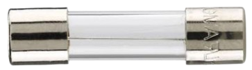
A 2A fuse is a protective device designed to interrupt an electrical circuit when the current flowing through it exceeds 2 amperes. This interruption prevents damage to sensitive components, reduces the risk of overheating, and minimizes the chance of electrical fires. Fuses are essential in safeguarding electronic devices and systems by acting as a fail-safe mechanism.
Explore Projects Built with 2A Fuse
 Open Project in Cirkit Designer
 Open Project in Cirkit Designer
 Open Project in Cirkit Designer
 Open Project in Cirkit Designer
Explore Projects Built with 2A Fuse
Open Project in Cirkit DesignerOpen Project in Cirkit DesignerOpen Project in Cirkit DesignerOpen Project in Cirkit DesignerCommon Applications and Use Cases
- Power supplies for electronic devices
- Protection of sensitive components in circuits
- Automotive electrical systems
- Household appliances
- Industrial equipment and machinery
Technical Specifications
The following table outlines the key technical details of a typical 2A fuse:
| Parameter | Specification |
|---|---|
| Rated Current | 2 Amperes |
| Rated Voltage | Typically 250V AC or 32V DC |
| Breaking Capacity | Varies (e.g., 35A at 250V AC) |
| Fuse Type | Fast-blow (F) or Slow-blow (T) |
| Material | Glass or ceramic body with metal caps |
| Operating Temperature | -55°C to +125°C |
| Dimensions | Standard sizes (e.g., 5x20mm, 6.3x32mm) |
Pin Configuration and Descriptions
A fuse does not have traditional pins like ICs or transistors. Instead, it has two metallic end caps or terminals that connect to the circuit. These terminals are typically soldered onto a PCB or inserted into a fuse holder.
| Terminal | Description |
|---|---|
| Terminal 1 | Input terminal for current flow |
| Terminal 2 | Output terminal for current flow |
Usage Instructions
How to Use the 2A Fuse in a Circuit
- Determine the Fuse Type: Choose between fast-blow (F) or slow-blow (T) based on the application:
- Use fast-blow fuses for circuits with steady current and no surges.
- Use slow-blow fuses for circuits with inrush currents (e.g., motors or transformers).
- Select the Correct Fuse Holder: Ensure the fuse holder matches the fuse's size and voltage/current rating.
- Insert the Fuse: Place the fuse into the holder or solder it directly onto the PCB.
- Verify Circuit Design: Ensure the fuse is placed in series with the load to protect it effectively.
- Test the Circuit: Power on the circuit and verify that the fuse operates as intended.
Important Considerations and Best Practices
- Always use a fuse with the correct current and voltage rating for your application.
- Avoid bypassing or shorting the fuse, as this defeats its protective purpose.
- Replace a blown fuse with one of the same type and rating.
- For circuits connected to microcontrollers like Arduino, ensure the fuse protects both the microcontroller and any connected peripherals.
Example: Using a 2A Fuse with an Arduino UNO
When powering an Arduino UNO from an external power supply, you can add a 2A fuse in series with the power input to protect the board from overcurrent conditions.
Circuit Diagram
[Power Supply] --- [2A Fuse] --- [Arduino UNO Vin Pin]
Arduino Code Example
The fuse itself does not require code, but here is an example of monitoring the power supply voltage to detect potential issues:
// Example code to monitor input voltage on Arduino UNO
const int voltagePin = A0; // Analog pin to read voltage
float voltage = 0.0;

void setup() {
  Serial.begin(9600); // Initialize serial communication
}

void loop() {
  int sensorValue = analogRead(voltagePin); // Read analog input
  voltage = sensorValue * (5.0 / 1023.0);   // Convert to voltage
  Serial.print("Input Voltage: ");
  Serial.print(voltage);
  Serial.println(" V");

  delay(1000); // Wait 1 second before next reading
}
Troubleshooting and FAQs
Common Issues
Fuse Blows Frequently
- Cause: The circuit may be drawing more than 2A due to a fault or incorrect design.
- Solution: Check the circuit for short circuits or components drawing excessive current. Use a higher-rated fuse only if the circuit design allows.
Fuse Does Not Blow When Expected
- Cause: The fuse may be incorrectly rated or defective.
- Solution: Verify the fuse's current and voltage ratings. Replace with a properly rated fuse.
Fuse Holder Overheats
- Cause: Poor contact between the fuse and holder.
- Solution: Ensure the fuse is securely seated in the holder. Replace the holder if necessary.
FAQs
Q: Can I use a 2A fuse in place of a higher-rated fuse?
A: No, using a 2A fuse in place of a higher-rated fuse may cause it to blow prematurely, disrupting the circuit unnecessarily.
Q: How do I know if a fuse is blown?
A: Inspect the fuse visually for a broken filament (in glass fuses) or use a multimeter to check for continuity.
Q: Can I use a 2A fuse for both AC and DC circuits?
A: Yes, but ensure the fuse's voltage rating is suitable for the circuit's operating voltage (e.g., 250V AC or 32V DC).