How to Use Arduino Development Board V4.0 Chip CP2102: Examples, Pinouts, and Specs
Introduction
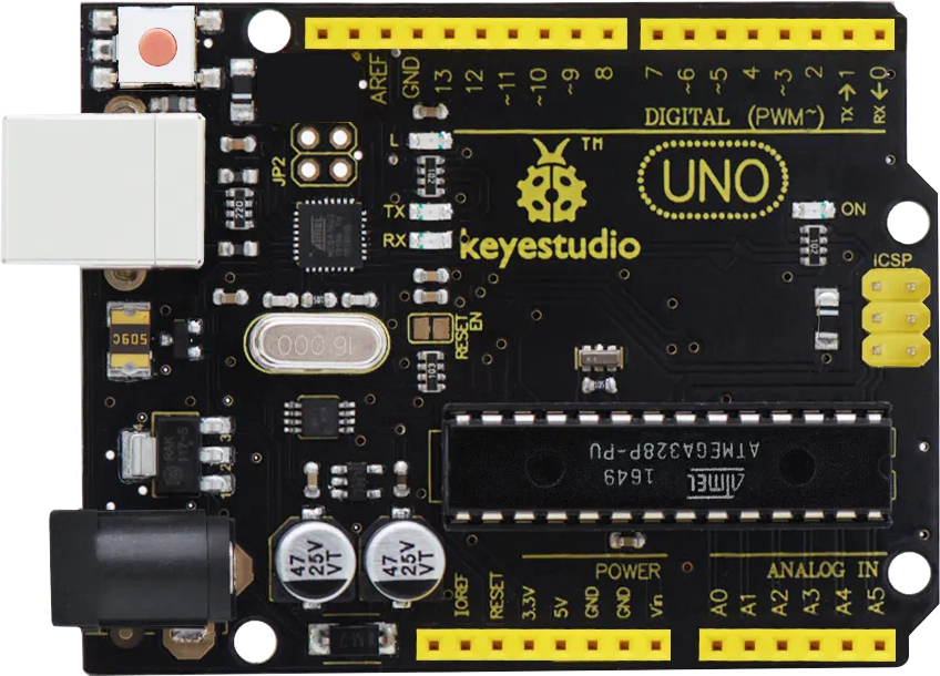
The Arduino Development Board V4.0 Chip CP2102 (Manufacturer: Keyestudio, Part ID: KS0497) is a versatile development board designed for prototyping and learning in the field of electronics and embedded systems. It features the CP2102 USB-to-UART bridge chip, which facilitates seamless communication between a computer's USB port and the board's UART interface. This board is ideal for programming, debugging, and serial communication with microcontrollers.
Explore Projects Built with Arduino Development Board V4.0 Chip CP2102
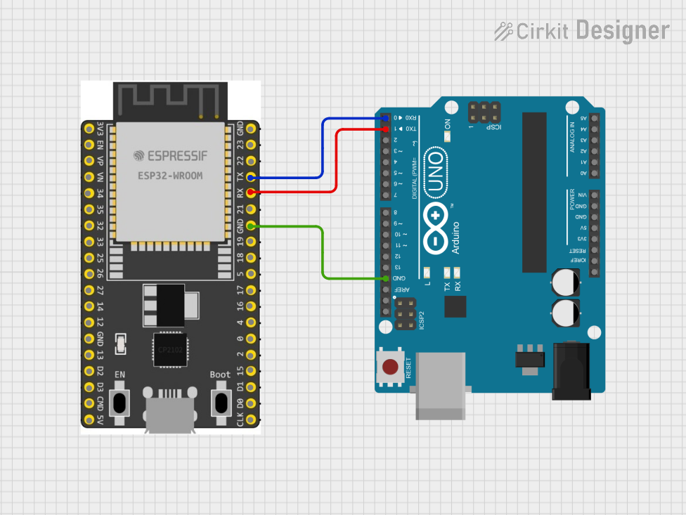
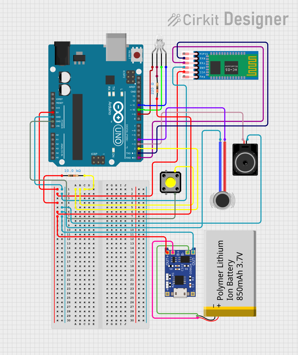

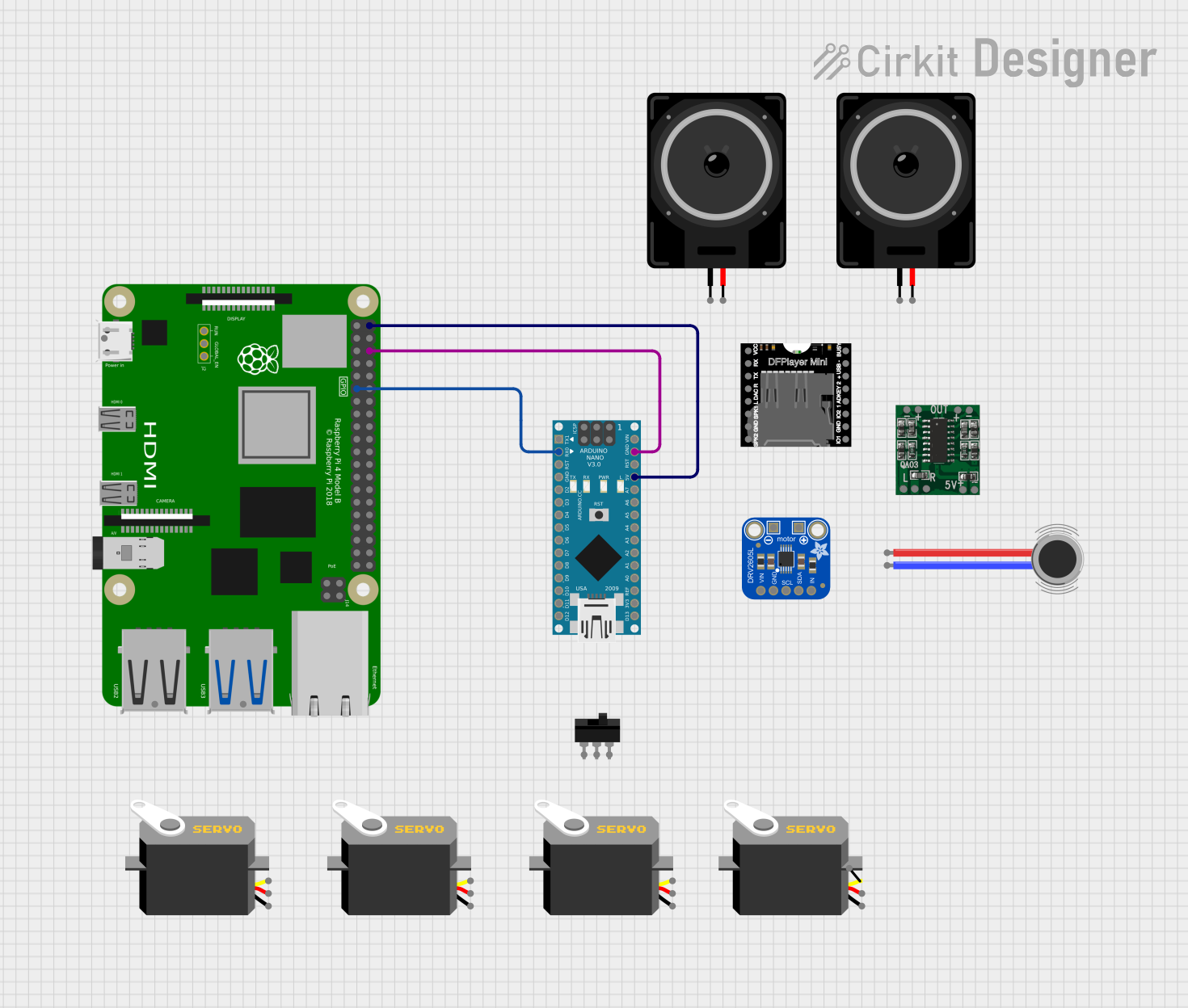
Explore Projects Built with Arduino Development Board V4.0 Chip CP2102
Common Applications and Use Cases
- Prototyping and testing embedded systems
- Serial communication with microcontrollers
- Programming Arduino-compatible boards
- Educational projects and learning environments
- IoT (Internet of Things) device development
Technical Specifications
Key Technical Details
- Microcontroller Compatibility: Fully compatible with Arduino IDE
- USB-to-UART Bridge Chip: Silicon Labs CP2102
- Operating Voltage: 5V (via USB) or 7-12V (via external power supply)
- Digital I/O Pins: 14 (6 of which support PWM output)
- Analog Input Pins: 6
- Clock Speed: 16 MHz
- USB Connector: Micro-USB
- Power Supply Options: USB or external DC power jack
- Dimensions: 68.6mm x 53.4mm
Pin Configuration and Descriptions
The Arduino Development Board V4.0 features a standard pinout compatible with most Arduino shields. Below is the pin configuration:
Digital Pins
| Pin Number | Label | Description |
|---|---|---|
| D0 - D1 | RX, TX | UART communication pins |
| D2 - D13 | Digital I/O | General-purpose digital input/output |
| D3, D5, D6, D9, D10, D11 | PWM | Pulse Width Modulation capable pins |
Analog Pins
| Pin Number | Label | Description |
|---|---|---|
| A0 - A5 | Analog In | Analog input pins (10-bit resolution) |
Power Pins
| Pin Label | Description |
|---|---|
| VIN | Input voltage (7-12V) |
| 5V | Regulated 5V output |
| 3.3V | Regulated 3.3V output |
| GND | Ground |
Other Pins
| Pin Label | Description |
|---|---|
| RESET | Resets the microcontroller |
| IOREF | Provides voltage reference for shields |
Usage Instructions
How to Use the Component in a Circuit
Powering the Board:
- Connect the board to your computer using a Micro-USB cable for 5V power.
- Alternatively, use an external DC power supply (7-12V) via the VIN pin or DC jack.
Programming the Board:
- Install the Arduino IDE on your computer.
- Install the CP2102 driver (available on the Silicon Labs website) to enable USB-to-UART communication.
- Select the correct board (e.g., "Arduino Uno") and COM port in the Arduino IDE.
- Write or load your sketch in the IDE and upload it to the board.
Connecting Peripherals:
- Use the digital and analog pins to connect sensors, actuators, and other peripherals.
- Ensure proper voltage levels and current requirements for connected devices.
Serial Communication:
- Use the RX and TX pins for UART communication with other devices.
- The Serial Monitor in the Arduino IDE can be used to send and receive data.
Important Considerations and Best Practices
- Always check the polarity and voltage of external power supplies to avoid damaging the board.
- Avoid connecting high-current devices directly to the I/O pins; use transistors or relays if needed.
- Use the onboard reset button to restart the microcontroller if it becomes unresponsive.
- Ensure the CP2102 driver is correctly installed to avoid communication issues.
Example Code for Arduino UNO
Below is an example sketch to demonstrate serial communication using the CP2102 chip:
// Example: Serial Communication with Arduino Development Board V4.0
// This sketch sends a message to the Serial Monitor every second.

void setup() {
  Serial.begin(9600); // Initialize serial communication at 9600 baud
  Serial.println("Arduino Development Board V4.0 Ready!");
  // Print a message to the Serial Monitor
}

void loop() {
  Serial.println("Hello, world!"); // Send a message to the Serial Monitor
  delay(1000); // Wait for 1 second
}
Troubleshooting and FAQs
Common Issues and Solutions
The board is not recognized by the computer:
- Ensure the CP2102 driver is installed correctly.
- Try a different USB cable or port.
- Check the Device Manager (Windows) or System Information (Mac) for the COM port.
Unable to upload sketches:
- Verify the correct board and COM port are selected in the Arduino IDE.
- Press the reset button on the board before uploading.
- Ensure no other application is using the COM port.
Serial communication is not working:
- Confirm the baud rate in the Arduino sketch matches the Serial Monitor.
- Check the connections to the RX and TX pins.
The board is overheating:
- Ensure the input voltage does not exceed 12V.
- Disconnect high-current devices from the I/O pins.
FAQs
Q: Can I use this board with 3.3V sensors?
A: Yes, the board provides a 3.3V output pin for powering 3.3V sensors. However, ensure the sensor's I/O pins are 5V-tolerant or use a level shifter.
Q: Is the CP2102 driver compatible with all operating systems?
A: The CP2102 driver is compatible with Windows, macOS, and Linux. Visit the Silicon Labs website for the latest driver version.
Q: Can I use this board with Arduino shields?
A: Yes, the board is fully compatible with most Arduino shields due to its standard pinout.
Q: What is the maximum current output of the 5V and 3.3V pins?
A: The 5V pin can supply up to 500mA, and the 3.3V pin can supply up to 50mA, depending on the power source.
This concludes the documentation for the Arduino Development Board V4.0 Chip CP2102.