How to Use linea de 8 sensores infrarojos: Examples, Pinouts, and Specs
Introduction
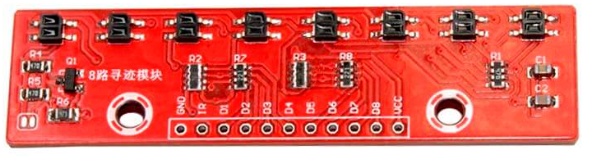
The Linea de 8 Sensores Infrarrojos (QTR-8), manufactured by Aeduino, is a compact and versatile sensor array consisting of 8 infrared (IR) sensors. Each sensor in the array is capable of emitting and detecting infrared light, making it ideal for applications such as obstacle detection, line-following robots, and distance measurement. The QTR-8 is designed to provide high accuracy and reliability in detecting reflective surfaces or objects.
Explore Projects Built with linea de 8 sensores infrarojos

Explore Projects Built with linea de 8 sensores infrarojos
Common Applications and Use Cases
- Line-following robots for navigation
- Obstacle detection in autonomous vehicles
- Edge detection in industrial automation
- Proximity sensing for robotics
- Object tracking and sorting systems
Technical Specifications
The QTR-8 sensor array is designed to operate efficiently in a variety of environments. Below are its key technical details:
General Specifications
| Parameter | Value |
|---|---|
| Manufacturer | Aeduino |
| Part ID | QTR-8 |
| Number of Sensors | 8 |
| Operating Voltage | 3.3V to 5V |
| Operating Current | ~100 mA (typical) |
| Output Type | Analog or Digital (selectable) |
| Detection Range | 1 mm to 10 mm (optimal) |
| Sensor Type | Infrared (IR) emitter and receiver pair |
| Dimensions | 80 mm x 10 mm x 3 mm |
Pin Configuration and Descriptions
The QTR-8 sensor array has a 10-pin interface. The pinout is as follows:
| Pin Number | Name | Description |
|---|---|---|
| 1 | VCC | Power supply input (3.3V to 5V) |
| 2 | GND | Ground connection |
| 3 | OUT1 | Analog/Digital output for sensor 1 |
| 4 | OUT2 | Analog/Digital output for sensor 2 |
| 5 | OUT3 | Analog/Digital output for sensor 3 |
| 6 | OUT4 | Analog/Digital output for sensor 4 |
| 7 | OUT5 | Analog/Digital output for sensor 5 |
| 8 | OUT6 | Analog/Digital output for sensor 6 |
| 9 | OUT7 | Analog/Digital output for sensor 7 |
| 10 | OUT8 | Analog/Digital output for sensor 8 |
Usage Instructions
The QTR-8 sensor array is straightforward to use in a variety of circuits. Below are the steps and best practices for integrating it into your project:
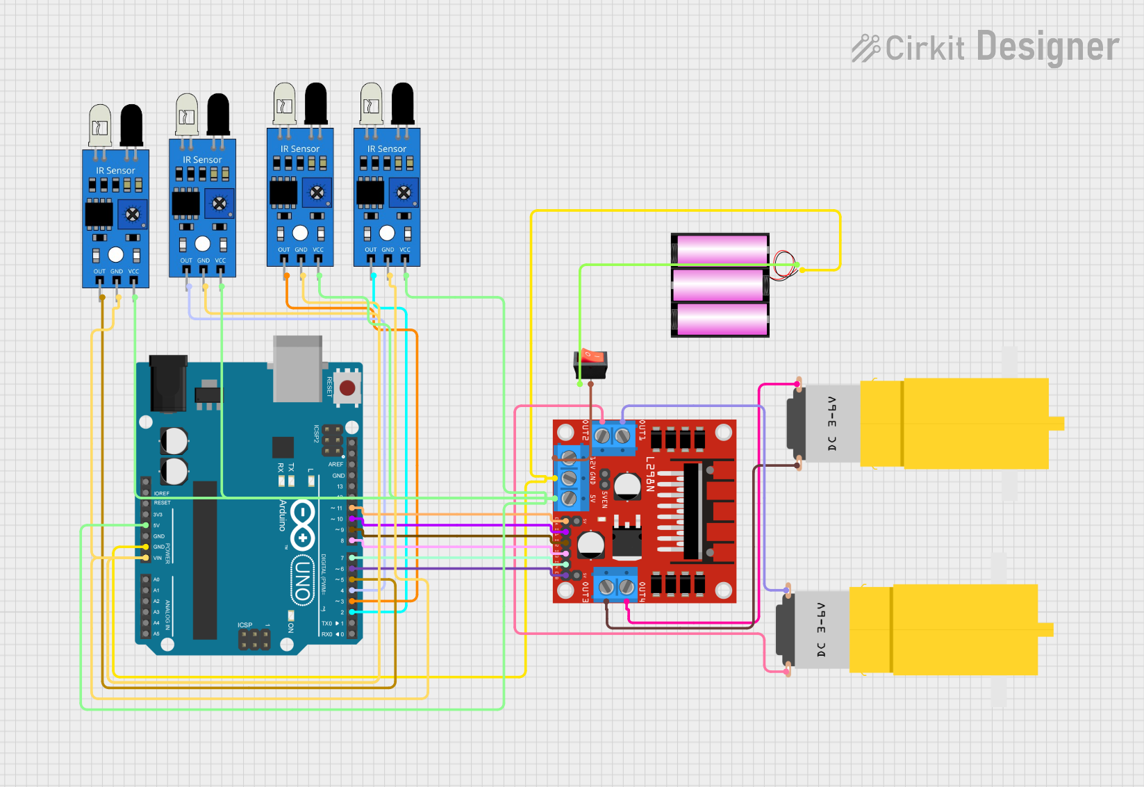
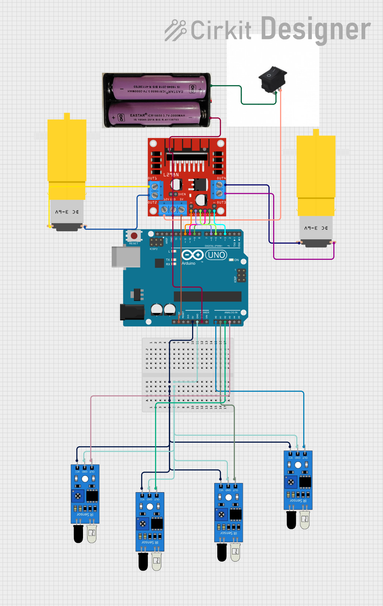
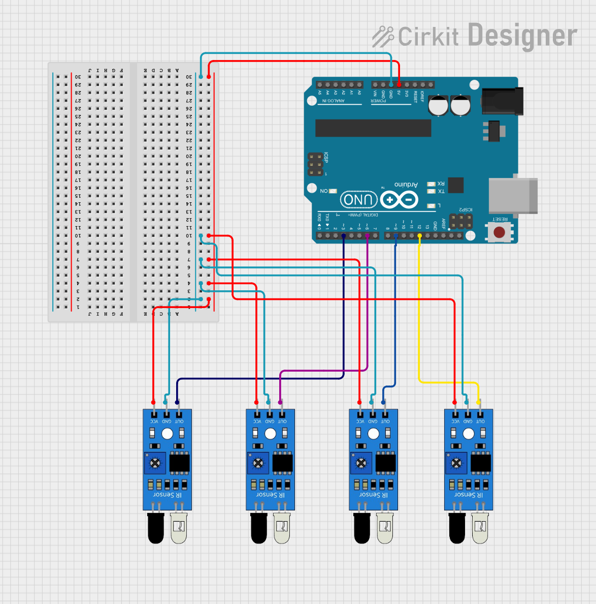
Connecting the QTR-8 to an Arduino UNO
- Power the Sensor Array: Connect the
VCCpin to the 5V pin on the Arduino UNO and theGNDpin to the Arduino's GND. - Connect Sensor Outputs: Connect the
OUT1toOUT8pins to the desired analog or digital input pins on the Arduino UNO. - Select Output Mode: The QTR-8 can output either analog or digital signals. Use a pull-up resistor or configure the Arduino pins accordingly for digital mode.
Sample Arduino Code
The following code demonstrates how to read values from the QTR-8 sensor array using an Arduino UNO:
// Include necessary libraries
// No external libraries are required for basic analog reading

// Define the sensor pins
const int sensorPins[8] = {A0, A1, A2, A3, A4, A5, A6, A7}; // Analog pins on Arduino

void setup() {
  Serial.begin(9600); // Initialize serial communication for debugging
  for (int i = 0; i < 8; i++) {
    pinMode(sensorPins[i], INPUT); // Set sensor pins as input
  }
}

void loop() {
  int sensorValues[8]; // Array to store sensor readings

  // Read values from each sensor
  for (int i = 0; i < 8; i++) {
    sensorValues[i] = analogRead(sensorPins[i]); // Read analog value
  }

  // Print sensor values to the Serial Monitor
  Serial.print("Sensor Values: ");
  for (int i = 0; i < 8; i++) {
    Serial.print(sensorValues[i]);
    Serial.print(" ");
  }
  Serial.println(); // New line for better readability

  delay(100); // Small delay to avoid overwhelming the Serial Monitor
}
Important Considerations and Best Practices
- Power Supply: Ensure a stable power supply to avoid fluctuations in sensor readings.
- Surface Reflectivity: The QTR-8 works best with surfaces that have a high contrast in reflectivity (e.g., black and white lines).
- Distance Calibration: Adjust the height of the sensor array to maintain an optimal detection range (1 mm to 10 mm).
- Ambient Light: Minimize ambient IR light interference by shielding the sensor array or using it in controlled lighting conditions.
Troubleshooting and FAQs
Common Issues and Solutions
Inconsistent Readings:
- Cause: Ambient IR light interference or unstable power supply.
- Solution: Use the sensor in a controlled lighting environment and ensure a stable power source.
No Output from Sensors:
- Cause: Incorrect wiring or damaged components.
- Solution: Double-check all connections and ensure the sensor array is powered correctly.
Low Sensitivity:
- Cause: Sensor array is too far from the surface.
- Solution: Adjust the height of the sensor array to be within the optimal range (1 mm to 10 mm).
Output Values Not Changing:
- Cause: Reflective surface not detected or sensor malfunction.
- Solution: Test the sensor with a known reflective surface and verify its functionality.
FAQs
Q: Can the QTR-8 be used with a 3.3V microcontroller?
A: Yes, the QTR-8 is compatible with both 3.3V and 5V systems. Ensure the microcontroller's input pins can read the sensor's output voltage levels.
Q: How do I switch between analog and digital output modes?
A: The QTR-8 outputs analog signals by default. To use digital mode, configure the Arduino pins with a threshold value in your code to interpret the analog signals as HIGH or LOW.
Q: What is the maximum detection range of the QTR-8?
A: The QTR-8 has an optimal detection range of 1 mm to 10 mm. Beyond this range, accuracy may decrease.
Q: Can I use fewer than 8 sensors in my project?
A: Yes, you can use as many sensors as needed by connecting only the required output pins to your microcontroller.
By following this documentation, you can effectively integrate the QTR-8 sensor array into your projects and troubleshoot any issues that arise.