How to Use Type C USB Port: Examples, Pinouts, and Specs
Introduction
The Type C USB Port is a versatile and reversible connector designed for modern electronic devices. It supports faster data transfer rates, higher power delivery, and improved durability compared to its predecessors (USB Type-A and Type-B). Its symmetrical design eliminates orientation issues, making it user-friendly and reliable.
Explore Projects Built with Type C USB Port


Explore Projects Built with Type C USB Port
Common Applications and Use Cases
- Smartphones and Tablets: Charging and data transfer.
- Laptops and Desktops: Connecting peripherals, external storage, and displays.
- Power Delivery: Supporting up to 100W for fast charging of devices.
- Audio and Video Transmission: Compatible with HDMI, DisplayPort, and Thunderbolt standards.
- IoT Devices: Powering and interfacing with smart devices.
Technical Specifications
Key Technical Details
- Connector Type: USB Type-C
- Data Transfer Rates: Up to 10 Gbps (USB 3.1 Gen 2) or 40 Gbps (Thunderbolt 3/4)
- Power Delivery: Up to 100W (20V, 5A) with USB Power Delivery (USB-PD) protocol
- Reversibility: Symmetrical design for easy insertion
- Durability: Rated for 10,000+ insertion/removal cycles
- Backward Compatibility: Supports USB 2.0, 3.0, and 3.1 standards with appropriate adapters
Pin Configuration and Descriptions
The Type C USB Port has 24 pins, divided into two symmetrical rows. Below is a simplified pinout:
| Pin Number | Name | Description |
|---|---|---|
| A1, B1 | GND | Ground |
| A4, B4 | VBUS | Power supply (up to 20V, 5A) |
| A5, B5 | CC1, CC2 | Configuration channel for cable orientation and power |
| A6, B6 | D+ | USB 2.0 differential pair (positive) |
| A7, B7 | D- | USB 2.0 differential pair (negative) |
| A8, B8 | SBU1, SBU2 | Sideband use for alternate modes (e.g., audio/video) |
| A2, A3, B2, B3 | TX+/TX-, RX+/RX- | High-speed differential pairs for USB 3.1/Thunderbolt |
Usage Instructions
How to Use the Type C USB Port in a Circuit
- Power Supply: Ensure the VBUS pin is connected to a regulated power source. For USB-PD, use a compatible controller to negotiate power levels.
- Data Lines: Connect the D+ and D- pins for USB 2.0 communication. For USB 3.1 or higher, connect the TX/RX differential pairs.
- Configuration Channel (CC): Use the CC pins to detect cable orientation and negotiate power delivery. A pull-up or pull-down resistor is typically required.
- Alternate Modes: For video or other protocols, configure the SBU pins and high-speed lanes accordingly.
Important Considerations and Best Practices
- Voltage Regulation: Use a USB-PD controller IC to safely manage power delivery.
- Cable Quality: Ensure the cable supports the required data rate and power level.
- Overcurrent Protection: Add fuses or current-limiting ICs to protect the circuit.
- Signal Integrity: Use proper PCB layout techniques to minimize noise and interference on high-speed data lines.
- Reversibility: Design the circuit to handle both orientations of the connector.
Example: Connecting a Type C USB Port to an Arduino UNO
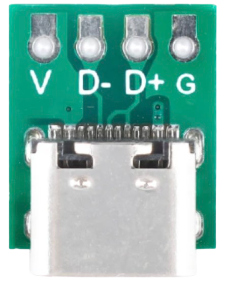
While the Arduino UNO does not natively support USB Type-C, you can use a USB Type-C breakout board for power or data communication. Below is an example of using the Type-C port for power:
// Example: Powering an Arduino UNO via USB Type-C
// Ensure the Type-C breakout board is connected to the Arduino's VIN and GND pins.
// This setup allows the Arduino to be powered by a USB Type-C power source.

void setup() {
  // No specific setup required for power-only connections
}

void loop() {
  // Your main code here
}
For data communication, additional USB-to-serial converters or USB host shields may be required.
Troubleshooting and FAQs
Common Issues and Solutions
Device Not Recognized:
- Cause: Incorrect wiring of data lines or missing pull-up/pull-down resistors on CC pins.
- Solution: Verify connections and ensure proper resistor values are used.
Overheating:
- Cause: Excessive current draw or poor thermal management.
- Solution: Check power delivery settings and ensure adequate heat dissipation.
No Power Delivery:
- Cause: Incompatible cable or missing USB-PD controller.
- Solution: Use a certified USB Type-C cable and implement a USB-PD controller IC.
Data Transfer Issues:
- Cause: Signal integrity problems or incompatible devices.
- Solution: Use high-quality cables and ensure proper PCB layout for high-speed signals.
FAQs
Q: Can I use a Type C USB Port for both power and data simultaneously?
A: Yes, the Type C USB Port is designed to handle both power delivery and data transfer simultaneously.Q: Do I need a special cable for USB Power Delivery?
A: Yes, ensure the cable is USB-PD certified to support higher power levels.Q: How do I implement alternate modes like HDMI or DisplayPort?
A: Use a compatible controller IC to configure the SBU and high-speed pins for the desired protocol.
By following this documentation, you can effectively integrate and troubleshoot the Type C USB Port in your projects.