How to Use SimComA7670C: Examples, Pinouts, and Specs
Introduction
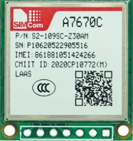
The SimCom A7670C is a compact GSM/GPRS module designed for IoT applications, offering reliable cellular connectivity across multiple frequency bands. This module is ideal for applications requiring low power consumption, such as battery-operated devices, and features a built-in TCP/IP stack for seamless integration into various systems. Its small form factor and robust performance make it a popular choice for developers working on smart devices, remote monitoring, and industrial IoT solutions.
Explore Projects Built with SimComA7670C

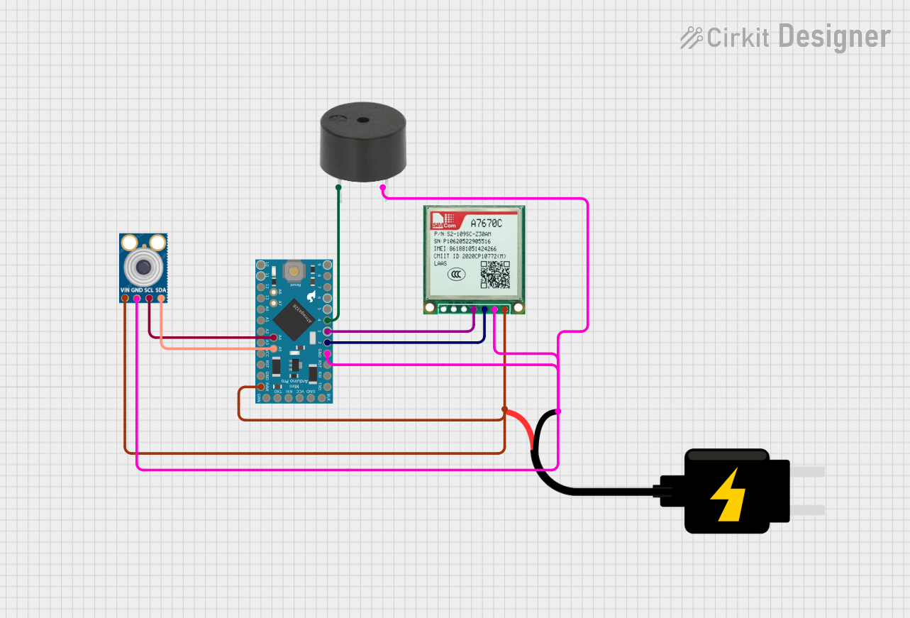
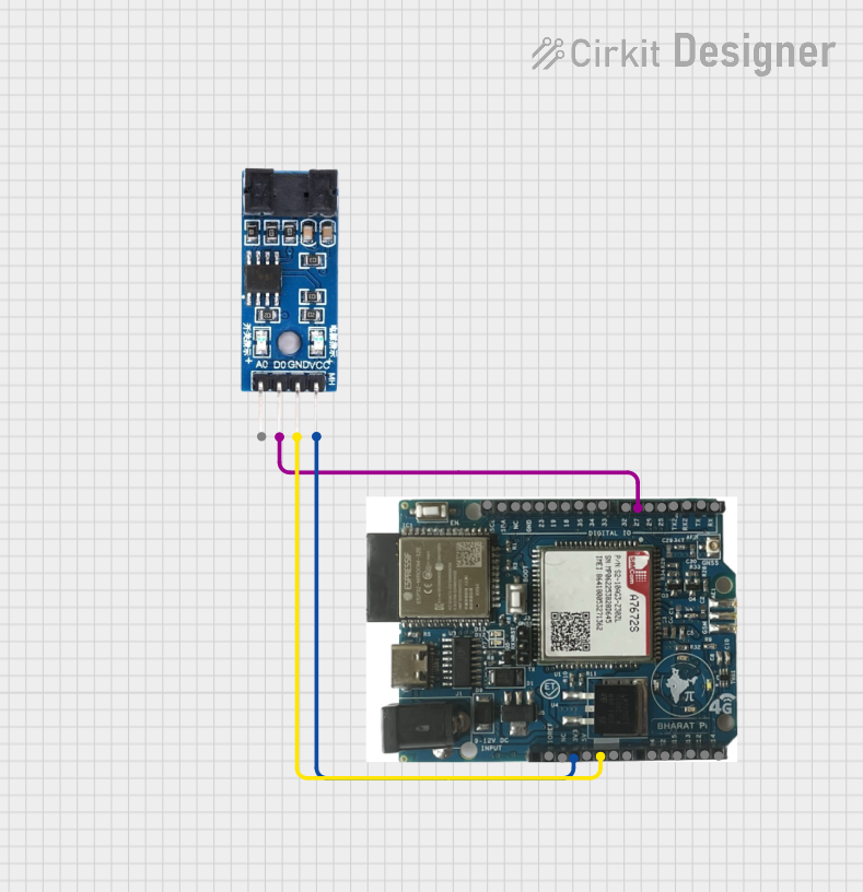
Explore Projects Built with SimComA7670C
Common Applications
- Smart metering and remote monitoring
- Asset tracking and fleet management
- Home automation and smart appliances
- Industrial IoT and machine-to-machine (M2M) communication
- Wearable devices and portable electronics
Technical Specifications
Key Technical Details
| Parameter | Specification |
|---|---|
| Manufacturer | SIMCOM |
| Part Number | A7670C |
| Cellular Technology | GSM/GPRS |
| Frequency Bands | GSM 850/900/1800/1900 MHz |
| Data Transmission | GPRS multi-slot class 12, coding schemes CS1-CS4 |
| Power Supply Voltage | 3.4V to 4.2V |
| Operating Temperature | -40°C to +85°C |
| Dimensions | 19.8mm × 19.8mm × 2.15mm |
| Power Consumption | - Idle: ~1.2mA |
| - Active (GPRS): ~350mA | |
| Communication Interfaces | UART, GPIO, ADC |
| TCP/IP Stack | Built-in |
| SIM Card Interface | 1.8V/3.0V SIM card support |
| Antenna Interface | 50Ω impedance |
Pin Configuration and Descriptions
The A7670C module has a total of 42 pins. Below is a summary of key pins:
| Pin Number | Pin Name | Description |
|---|---|---|
| 1 | VCC | Power supply input (3.4V to 4.2V) |
| 2 | GND | Ground connection |
| 3 | TXD | UART transmit data |
| 4 | RXD | UART receive data |
| 5 | RTS | UART request to send |
| 6 | CTS | UART clear to send |
| 7 | SIM_VDD | SIM card power supply |
| 8 | SIM_CLK | SIM card clock |
| 9 | SIM_DATA | SIM card data I/O |
| 10 | SIM_RST | SIM card reset |
| 11 | ADC_IN | Analog-to-digital converter input |
| 12 | GPIO1 | General-purpose input/output |
| 13 | GPIO2 | General-purpose input/output |
| 14 | NET_STATUS | Network status indicator |
| 15 | PWRKEY | Power-on key input |
| 16 | RESET | Reset input (active low) |
| 17 | ANT | Antenna interface (50Ω impedance) |
Usage Instructions
How to Use the A7670C in a Circuit
- Power Supply: Ensure the module is powered with a stable voltage between 3.4V and 4.2V. Use decoupling capacitors near the VCC pin to minimize noise.
- Antenna Connection: Connect a 50Ω impedance antenna to the ANT pin for optimal signal reception and transmission.
- SIM Card Interface: Insert a 1.8V or 3.0V SIM card and connect the SIM_VDD, SIM_CLK, SIM_DATA, and SIM_RST pins to the corresponding SIM card interface.
- UART Communication: Connect the TXD and RXD pins to a microcontroller or host device for serial communication. Use RTS and CTS for hardware flow control if required.
- Power-On Sequence: Pull the PWRKEY pin low for at least 1 second to power on the module. Monitor the NET_STATUS pin to check network connectivity.
Important Considerations
- Power Supply: Use a low-noise power supply to avoid interference with the module's operation.
- Antenna Placement: Place the antenna away from high-frequency components to reduce signal degradation.
- UART Voltage Levels: Ensure the UART voltage levels are compatible with the host device (typically 3.3V or 5V).
- Firmware Updates: Periodically check for firmware updates from SIMCOM to ensure optimal performance and compatibility.
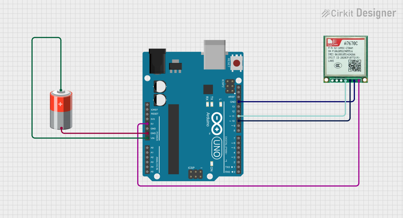
Example: Connecting A7670C to Arduino UNO
Below is an example of how to interface the A7670C module with an Arduino UNO for sending an SMS:
Circuit Connections
| A7670C Pin | Arduino Pin |
|---|---|
| TXD | RX (Pin 0) |
| RXD | TX (Pin 1) |
| GND | GND |
| VCC | 5V (via a voltage regulator to step down to 4.2V) |
Arduino Code
#include <SoftwareSerial.h>

// Define RX and TX pins for SoftwareSerial
SoftwareSerial simModule(10, 11); // RX = Pin 10, TX = Pin 11

void setup() {
  // Initialize serial communication with the module
  simModule.begin(9600);
  Serial.begin(9600); // For debugging via Serial Monitor

  // Power on the module
  Serial.println("Initializing A7670C...");
  delay(1000);

  // Send AT command to check communication
  simModule.println("AT");
  delay(1000);
  while (simModule.available()) {
    Serial.write(simModule.read()); // Print module response to Serial Monitor
  }

  // Send SMS command
  simModule.println("AT+CMGF=1"); // Set SMS mode to text
  delay(1000);
  simModule.println("AT+CMGS=\"+1234567890\""); // Replace with recipient's phone number
  delay(1000);
  simModule.print("Hello from A7670C!"); // SMS content
  delay(1000);
  simModule.write(26); // Send Ctrl+Z to send the SMS
}

void loop() {
  // No actions in loop
}
Troubleshooting and FAQs
Common Issues and Solutions
Module Not Powering On
- Ensure the PWRKEY pin is pulled low for at least 1 second during startup.
- Verify the power supply voltage is within the 3.4V to 4.2V range.
No Network Connectivity
- Check the antenna connection and ensure it is securely attached.
- Verify the SIM card is inserted correctly and is active with sufficient balance.
No Response to AT Commands
- Confirm the UART connections (TXD, RXD) are correct.
- Ensure the baud rate matches the module's default (9600 bps).
High Power Consumption
- Check for unnecessary active connections or processes.
- Use the module's sleep mode to reduce power consumption during idle periods.
FAQs
Q: Can the A7670C module be used with 5V logic levels?
A: No, the A7670C operates at 3.3V logic levels. Use a level shifter if interfacing with a 5V system.
Q: How do I update the firmware?
A: Firmware updates can be performed using SIMCOM's official tools and a UART connection. Refer to the manufacturer's documentation for detailed instructions.
Q: Does the module support 4G or LTE?
A: No, the A7670C is a GSM/GPRS module and does not support 4G or LTE connectivity.
This concludes the documentation for the SimCom A7670C module. For further assistance, refer to the official SIMCOM datasheet or contact technical support.