How to Use SparkFun Servo Trigger: Examples, Pinouts, and Specs
Introduction
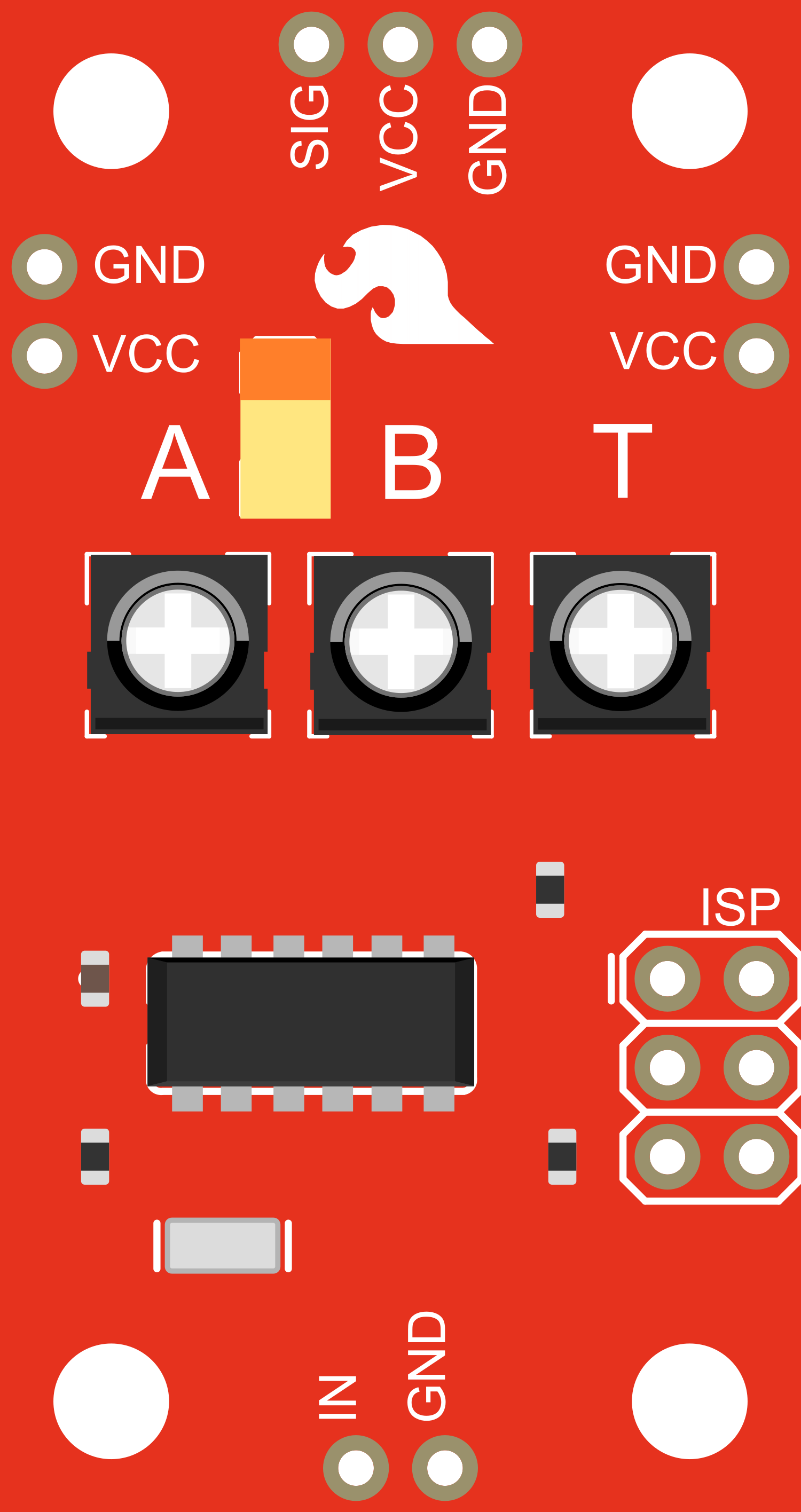
The SparkFun Servo Trigger is a versatile board designed to control hobbyist servo motors in response to external signals. It simplifies the process of making a servo move in response to a new position without the need for a microcontroller. With an onboard potentiometer, users can adjust the speed of the servo's movement. This component is ideal for creating simple automation projects, interactive displays, or robotics without complex programming.
Explore Projects Built with SparkFun Servo Trigger

Explore Projects Built with SparkFun Servo Trigger
Common Applications and Use Cases
- Automated displays and animatronics
- Robotics and RC vehicles
- Prototyping interactive projects
- Educational tools for teaching servo motor control
Technical Specifications
Key Technical Details
- Operating Voltage: 5V to 16V
- Output Current: Up to 3A (6A peak)
- Logic Input Voltage: 3.3V (high) or 0V (low)
- Control Signal: PWM, 1.5ms default width
Pin Configuration and Descriptions
| Pin Number | Name | Description |
|---|---|---|
| 1 | GND | Ground connection |
| 2 | VCC | Power supply input (5V to 16V) |
| 3 | IN | Trigger input (active-high) |
| 4 | OUT | Servo control signal output |
| 5 | A | Potentiometer wiper (speed control) |
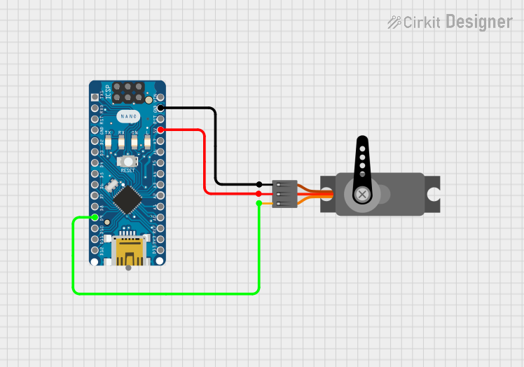
Usage Instructions
How to Use the Component in a Circuit
- Connect the
GNDpin to the ground of your power supply. - Connect the
VCCpin to a 5V to 16V power source. - Attach your servo's ground wire to the ground of your power supply, the power wire to the same power supply, and the control wire to the
OUTpin of the Servo Trigger. - Connect a trigger source (e.g., button, switch) to the
INpin. When the trigger is activated (set to high), the Servo Trigger will send a control signal to the servo.
Important Considerations and Best Practices
- Ensure that the power supply can handle the current requirements of your servo.
- Do not exceed the voltage rating of the Servo Trigger or the servo motor.
- Adjust the onboard potentiometer to set the desired servo speed before applying power.
- Use a pull-down resistor on the
INpin if the trigger source is not guaranteed to provide a low signal when inactive.
Troubleshooting and FAQs
Common Issues
- Servo not responding: Check all connections, ensure the power supply is adequate, and verify that the trigger signal is reaching the
INpin. - Erratic servo movement: This may be due to an unstable power supply or noise on the trigger signal. Ensure a clean and stable power source and signal.
Solutions and Tips for Troubleshooting
- If the servo behaves unexpectedly, recalibrate the potentiometer for speed control.
- Use a multimeter to verify the voltage levels at the
VCCandINpins. - Ensure that the servo's specifications are compatible with the Servo Trigger's output.
FAQs
Q: Can I use the Servo Trigger without an external trigger?
- A: Yes, you can manually control the servo by adjusting the onboard potentiometer.
Q: What is the maximum number of servos I can control with one Servo Trigger?
- A: The Servo Trigger is designed to control one servo per board. However, multiple boards can be used in parallel for controlling additional servos.
Q: Can I use the Servo Trigger with an Arduino?
- A: Absolutely. You can connect an Arduino's digital output to the
INpin to trigger the servo programmatically.
- A: Absolutely. You can connect an Arduino's digital output to the
Example Code for Arduino UNO
// Example code to control the SparkFun Servo Trigger with an Arduino UNO

const int triggerPin = 2; // Connect to the IN pin of the Servo Trigger

void setup() {
  pinMode(triggerPin, OUTPUT);
  digitalWrite(triggerPin, LOW); // Start with the trigger inactive
}

void loop() {
  digitalWrite(triggerPin, HIGH); // Activate the trigger
  delay(1000); // Wait for 1 second
  digitalWrite(triggerPin, LOW); // Deactivate the trigger
  delay(1000); // Wait for 1 second
}
Note: This code will toggle the servo position between two points every second. Adjust the delay and logic as needed for your specific application.
Remember to keep your code comments concise and within the 80 character line length limit. This ensures readability and maintainability of your code.