How to Use IR Sensor (Short Pins): Examples, Pinouts, and Specs
Introduction
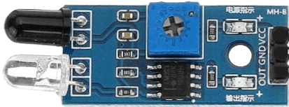
The IR Sensor (Short Pins) is an electronic component designed to detect infrared (IR) radiation. It is widely used in proximity sensing, object detection, and line-following robots. The compact design with short pins makes it ideal for space-constrained applications, such as small robots or embedded systems. This sensor operates by emitting infrared light and detecting the reflected signal from nearby objects.
Explore Projects Built with IR Sensor (Short Pins)
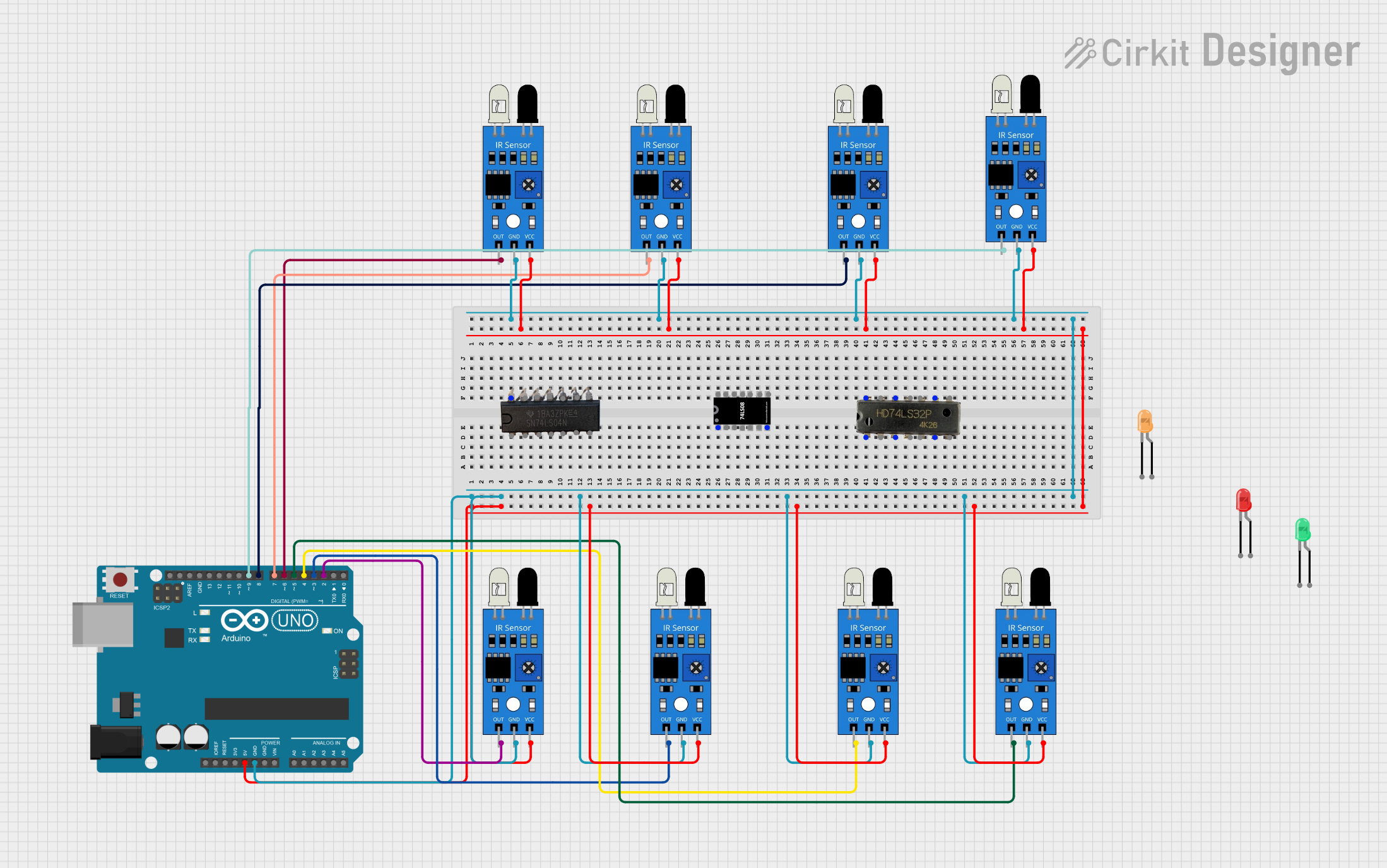
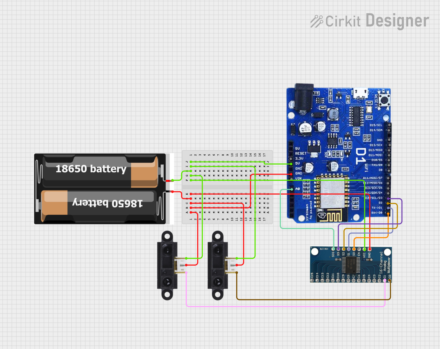
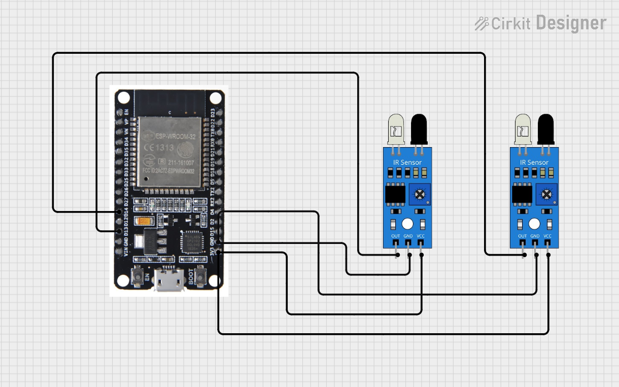
Explore Projects Built with IR Sensor (Short Pins)
Common Applications
- Obstacle detection in robotics
- Line-following robots
- Proximity sensing in automation systems
- Gesture recognition
- Object counting in conveyor systems
Technical Specifications
The following table outlines the key technical details of the IR Sensor (Short Pins):
| Parameter | Value |
|---|---|
| Operating Voltage | 3.3V to 5V |
| Operating Current | 20mA (typical) |
| Detection Range | 2cm to 30cm (adjustable) |
| Output Type | Digital (High/Low) |
| Wavelength of IR Light | 940nm |
| Dimensions | Compact with short pin design |
Pin Configuration
The IR Sensor (Short Pins) typically has three pins. The table below describes each pin:
| Pin | Name | Description |
|---|---|---|
| 1 | VCC | Power supply pin (3.3V to 5V) |
| 2 | GND | Ground pin |
| 3 | OUT | Digital output pin (High when no object is detected, Low when an object is detected) |
Usage Instructions
How to Use the IR Sensor in a Circuit
- Power the Sensor: Connect the VCC pin to a 3.3V or 5V power source and the GND pin to the ground of your circuit.
- Connect the Output: Attach the OUT pin to a digital input pin of your microcontroller or directly to an LED/buzzer for simple applications.
- Adjust the Sensitivity: Use the onboard potentiometer to adjust the detection range of the sensor. Turn it clockwise to increase the range and counterclockwise to decrease it.
- Test the Sensor: Place an object within the detection range and observe the output signal. The OUT pin will go LOW when an object is detected.
Important Considerations
- Ambient Light: Avoid using the sensor in environments with strong ambient IR light (e.g., direct sunlight), as it may interfere with detection.
- Distance Calibration: Always calibrate the sensor's detection range using the potentiometer for optimal performance in your specific application.
- Power Supply: Ensure a stable power supply to avoid erratic behavior.
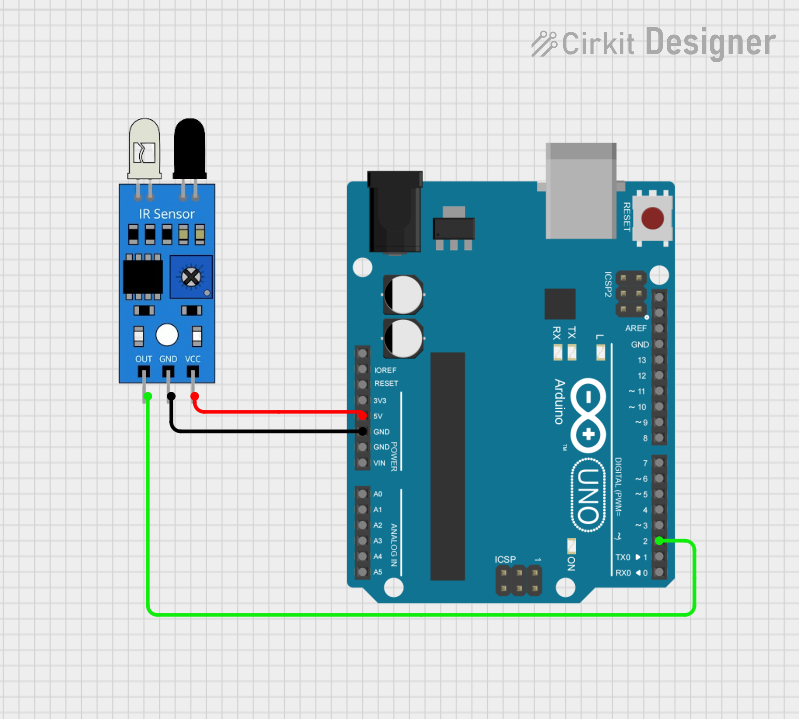
Example: Connecting to an Arduino UNO
Below is an example of how to connect and use the IR Sensor (Short Pins) with an Arduino UNO:
Circuit Connections
- Connect the VCC pin of the sensor to the 5V pin on the Arduino.
- Connect the GND pin of the sensor to the GND pin on the Arduino.
- Connect the OUT pin of the sensor to digital pin 2 on the Arduino.
Arduino Code
// IR Sensor Example Code for Arduino UNO
// This code reads the output of the IR sensor and turns on an LED when an object
// is detected within the sensor's range.

const int irSensorPin = 2;  // IR sensor output connected to digital pin 2
const int ledPin = 13;      // Onboard LED pin

void setup() {
  pinMode(irSensorPin, INPUT);  // Set IR sensor pin as input
  pinMode(ledPin, OUTPUT);      // Set LED pin as output
  Serial.begin(9600);           // Initialize serial communication for debugging
}

void loop() {
  int sensorValue = digitalRead(irSensorPin);  // Read the sensor output

  if (sensorValue == LOW) {
    // Object detected
    digitalWrite(ledPin, HIGH);  // Turn on the LED
    Serial.println("Object detected!");
  } else {
    // No object detected
    digitalWrite(ledPin, LOW);   // Turn off the LED
    Serial.println("No object detected.");
  }

  delay(100);  // Small delay for stability
}
Troubleshooting and FAQs
Common Issues and Solutions
Sensor Not Detecting Objects
- Cause: Incorrect power supply or loose connections.
- Solution: Verify that the VCC and GND pins are properly connected and the power supply is within the specified range.
Erratic Output
- Cause: Interference from ambient IR light or unstable power supply.
- Solution: Use the sensor in a controlled lighting environment and ensure a stable power source.
Short Detection Range
- Cause: Sensitivity not properly adjusted.
- Solution: Adjust the potentiometer to increase the detection range.
Output Always HIGH or LOW
- Cause: Faulty sensor or incorrect wiring.
- Solution: Check the wiring and replace the sensor if necessary.
FAQs
Q: Can the IR Sensor (Short Pins) detect transparent objects?
A: No, the sensor may struggle to detect transparent or highly reflective objects due to insufficient IR reflection.
Q: Is the sensor compatible with 3.3V systems?
A: Yes, the sensor operates within a voltage range of 3.3V to 5V, making it compatible with both 3.3V and 5V systems.
Q: How do I increase the detection range?
A: Use the onboard potentiometer to adjust the sensitivity. Turn it clockwise to increase the range.
Q: Can I use multiple IR sensors in the same circuit?
A: Yes, but ensure that the sensors are spaced apart to avoid interference from each other's IR signals.