How to Use LM358 Op-Amp: Examples, Pinouts, and Specs
Introduction
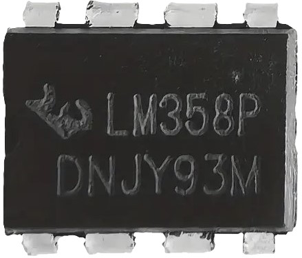
The LM358B is a dual operational amplifier (Op-Amp) designed by Texas Instruments, capable of operating with a single power supply and offering a wide range of voltage operations. This component is widely used in various electronic applications, including signal amplification, filters, voltage followers, and integrators due to its high voltage gain and low power consumption.
Explore Projects Built with LM358 Op-Amp
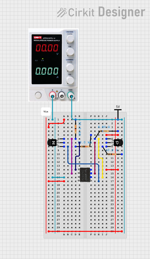
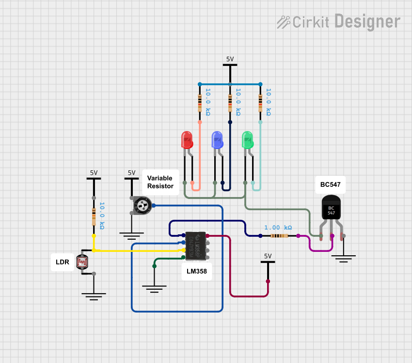
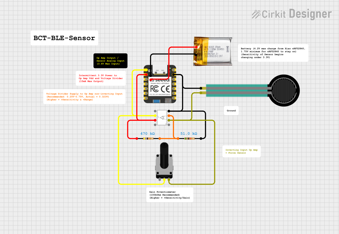
Explore Projects Built with LM358 Op-Amp
Common Applications
- Sensor amplifiers
- Active filters
- Audio pre-amplifiers
- Voltage followers
- Comparators
- Oscillators
Technical Specifications
Key Technical Details
- Power Supply Voltage Range: 3V to 32V (or ±1.5V to ±16V)
- Input Offset Voltage: 2 mV (Typical)
- Input Bias Current: 20 nA (Typical)
- Large Output Voltage Swing: 0V to V+ - 1.5V
- Slew Rate: 0.3 V/µs (Typical)
- Gain Bandwidth Product: 700 kHz (Typical)
Pin Configuration and Descriptions
| Pin Number | Name | Description |
|---|---|---|
| 1 | OUT1 | Output of Amplifier 1 |
| 2 | IN1- | Inverting Input of Amplifier 1 |
| 3 | IN1+ | Non-Inverting Input of Amplifier 1 |
| 4 | GND | Ground (0V) Reference |
| 5 | IN2+ | Non-Inverting Input of Amplifier 2 |
| 6 | IN2- | Inverting Input of Amplifier 2 |
| 7 | OUT2 | Output of Amplifier 2 |
| 8 | V+ | Positive Power Supply Voltage |
Usage Instructions
How to Use the LM358B in a Circuit
Power Supply Connection: Connect the positive power supply to pin 8 (V+) and the ground to pin 4 (GND). Ensure the supply voltage is within the specified range.
Input Signal: Apply the input signal to the non-inverting input (IN1+ or IN2+) for a non-inverted output or to the inverting input (IN1- or IN2-) for an inverted output.
Feedback Network: Connect a feedback network between the output (OUT1 or OUT2) and the inverting input (IN1- or IN2-) to set the gain of the amplifier.
Output: The amplified signal can be taken from the output pins (OUT1 or OUT2).
Important Considerations and Best Practices
- Bypass capacitors (typically 0.1 µF) should be placed close to the power supply pins to filter out noise.
- Avoid exceeding the maximum supply voltage to prevent damage to the Op-Amp.
- Use proper decoupling techniques to minimize the effects of power supply noise and ripple.
- Ensure that the differential input voltage and the input voltage range are within the limits specified in the datasheet.
Example Circuit: Non-Inverting Amplifier with Arduino UNO
// Define the analog input and output pins
const int analogInPin = A0; // Analog input pin connected to the Op-Amp
const int analogOutPin = 9; // PWM output pin connected to an LED

int sensorValue = 0;        // Value read from the Op-Amp
int outputValue = 0;        // Value output to the PWM (LED)

void setup() {
  // Initialize serial communications at 9600 bps:
  Serial.begin(9600);
}

void loop() {
  // Read the analog value from Op-Amp's output
  sensorValue = analogRead(analogInPin);
  // Map the analog value to a range suitable for PWM output
  outputValue = map(sensorValue, 0, 1023, 0, 255);
  // Change the analog out value
  analogWrite(analogOutPin, outputValue);

  // Print the results to the Serial Monitor
  Serial.print("sensor = ");
  Serial.print(sensorValue);
  Serial.print("\t output = ");
  Serial.println(outputValue);

  // Wait 2 milliseconds before the next loop
  delay(2);
}
Troubleshooting and FAQs
Common Issues
- Low Output Voltage Swing: Ensure the power supply voltage is sufficient and check for any saturation conditions.
- High Offset Voltage: This could be due to temperature variations or input bias current. Use offset nulling if necessary.
- Instability or Oscillation: Check the feedback network and ensure proper decoupling and layout techniques are used.
Solutions and Tips
- If the output is not as expected, verify the input signal and the feedback network.
- Use a multimeter to check the power supply voltage at the Op-Amp pins.
- Ensure that the input signals are within the common-mode range of the Op-Amp.
FAQs
Q: Can the LM358B be used with a dual power supply? A: Yes, the LM358B can operate with a dual power supply within the range of ±1.5V to ±16V.
Q: What is the difference between LM358 and LM358B? A: The LM358B is an enhanced version of the LM358 with improved specifications such as lower input offset voltage and wider temperature range.
Q: Is external compensation required for stability? A: No, the LM358B is internally compensated for unity gain stability.
Q: Can I use the LM358B for high-frequency applications? A: The LM358B has a bandwidth of 700 kHz, which may not be suitable for high-frequency applications. Consideration of the gain-bandwidth product is important for such applications.