How to Use 0.91" I2C OLED display: Examples, Pinouts, and Specs
Introduction
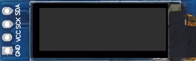
The 0.91" I2C OLED display, manufactured by HZWDONE, is a small, high-contrast display module that uses the I2C communication protocol. It is commonly used for displaying text, graphics, and other information in embedded systems and microcontroller projects. This display is particularly popular in applications where space is limited, and a clear, readable output is required.
Explore Projects Built with 0.91" I2C OLED display


Explore Projects Built with 0.91" I2C OLED display
Common Applications and Use Cases
- Wearable Devices: Due to its compact size, it is ideal for smartwatches and fitness trackers.
- IoT Projects: Useful for displaying sensor data and system status in Internet of Things devices.
- Prototyping: Frequently used in development boards like Arduino for quick visual feedback.
- Consumer Electronics: Suitable for small gadgets, remote controls, and other handheld devices.
Technical Specifications
Key Technical Details
| Parameter | Value |
|---|---|
| Display Type | OLED |
| Screen Size | 0.91 inches |
| Resolution | 128 x 32 pixels |
| Communication | I2C |
| Operating Voltage | 3.3V - 5V |
| Operating Current | 20mA (typical) |
| Viewing Angle | >160 degrees |
| Operating Temperature | -40°C to 85°C |
Pin Configuration and Descriptions
| Pin Number | Pin Name | Description |
|---|---|---|
| 1 | GND | Ground |
| 2 | VCC | Power Supply (3.3V - 5V) |
| 3 | SCL | I2C Clock Line |
| 4 | SDA | I2C Data Line |
Usage Instructions
How to Use the Component in a Circuit
Wiring the Display:
- Connect the GND pin of the display to the ground (GND) of the microcontroller.
- Connect the VCC pin of the display to the 3.3V or 5V power supply of the microcontroller.
- Connect the SCL pin of the display to the I2C clock line (SCL) of the microcontroller.
- Connect the SDA pin of the display to the I2C data line (SDA) of the microcontroller.
Programming the Display:
- Use an appropriate library to interface with the display. For Arduino, the
Adafruit_SSD1306andAdafruit_GFXlibraries are commonly used.
- Use an appropriate library to interface with the display. For Arduino, the
Important Considerations and Best Practices
- Power Supply: Ensure that the power supply voltage matches the display's operating voltage (3.3V - 5V).
- I2C Address: The default I2C address for the display is usually
0x3C. Verify this in the datasheet or by using an I2C scanner. - Library Compatibility: Make sure to use compatible libraries for your microcontroller platform.
- Initialization: Properly initialize the display in your code to avoid any display issues.
Example Code for Arduino UNO
#include <Wire.h>
#include <Adafruit_GFX.h>
#include <Adafruit_SSD1306.h>

// Define the screen dimensions
#define SCREEN_WIDTH 128
#define SCREEN_HEIGHT 32

// Create an instance of the display
Adafruit_SSD1306 display(SCREEN_WIDTH, SCREEN_HEIGHT, &Wire, -1);

void setup() {
  // Initialize the display
  if(!display.begin(SSD1306_I2C_ADDRESS, 0x3C)) {
    Serial.println(F("SSD1306 allocation failed"));
    for(;;);
  }

  // Clear the buffer
  display.clearDisplay();

  // Set text size and color
  display.setTextSize(1);
  display.setTextColor(SSD1306_WHITE);

  // Set cursor position
  display.setCursor(0, 0);

  // Display text
  display.println(F("Hello, World!"));

  // Update the display with the buffer content
  display.display();
}

void loop() {
  // Nothing to do here
}
Troubleshooting and FAQs
Common Issues Users Might Face
Display Not Turning On:
- Solution: Check the power connections and ensure the correct voltage is supplied.
No Display Output:
- Solution: Verify the I2C connections (SCL and SDA) and ensure the correct I2C address is used in the code.
Flickering or Unstable Display:
- Solution: Ensure stable power supply and proper initialization in the code.
Library Compatibility Issues:
- Solution: Make sure to use the latest versions of the
Adafruit_SSD1306andAdafruit_GFXlibraries.
- Solution: Make sure to use the latest versions of the
FAQs
Q1: What is the default I2C address of the display?
- The default I2C address is usually
0x3C. However, it is recommended to verify this using an I2C scanner.
Q2: Can I use this display with a 3.3V microcontroller?
- Yes, the display is compatible with both 3.3V and 5V microcontrollers.
Q3: How do I change the I2C address of the display?
- The I2C address is typically fixed. Refer to the datasheet for any possible address change options.
Q4: What libraries are recommended for Arduino?
- The
Adafruit_SSD1306andAdafruit_GFXlibraries are highly recommended for interfacing with this display.
By following this documentation, users should be able to effectively integrate and utilize the 0.91" I2C OLED display in their projects.