How to Use DigiPot: Examples, Pinouts, and Specs
Introduction
The DigiPot X9C103, manufactured by Intisil, is a digital potentiometer designed for applications requiring precise resistance adjustments through digital control. Unlike traditional mechanical potentiometers, the X9C103 allows for remote and programmable resistance changes, making it ideal for modern electronic systems. It features 100 taps (steps) for fine-grained control over resistance values.
Explore Projects Built with DigiPot
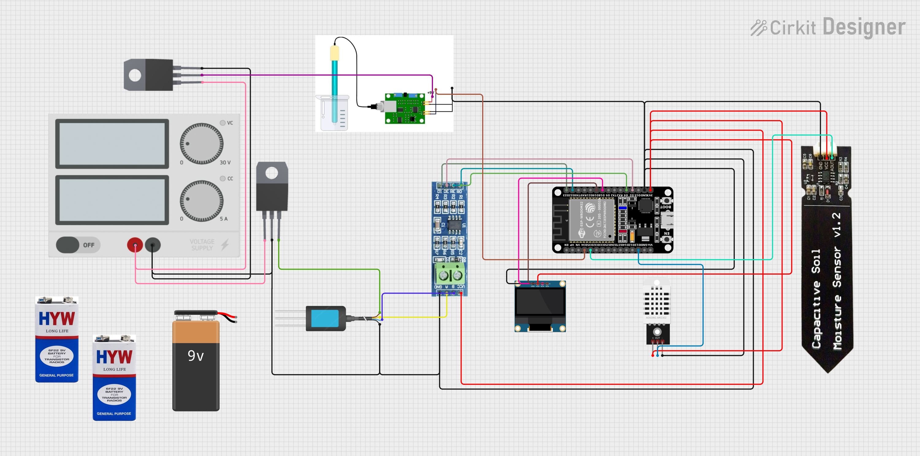
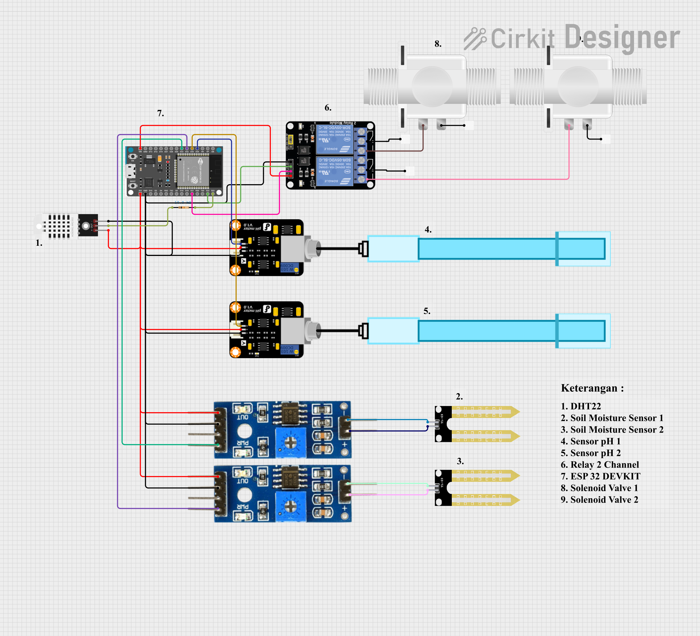
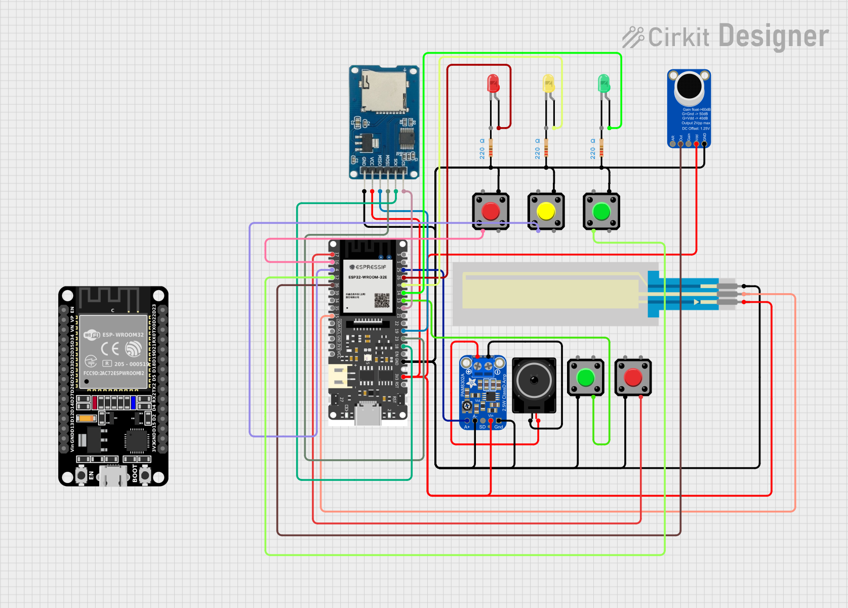
Explore Projects Built with DigiPot
Common Applications and Use Cases
- Audio volume control
- LED brightness adjustment
- Sensor calibration
- Programmable gain amplifiers
- Adjustable power supplies
- Remote-controlled devices
Technical Specifications
The X9C103 is a versatile component with the following key specifications:
| Parameter | Value |
|---|---|
| Resistance Range | 10 kΩ |
| Number of Taps | 100 |
| Wiper Resistance | 40 Ω (typical) |
| Supply Voltage (Vcc) | 2.7V to 5.5V |
| Maximum Current (Iwiper) | ±1 mA |
| Operating Temperature | -40°C to +85°C |
| Non-Volatile Memory | Yes (retains position after power-off) |
| Communication Interface | Up/Down digital control |
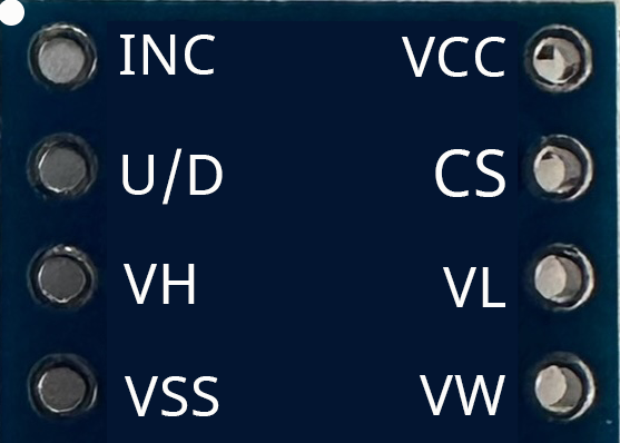
Pin Configuration and Descriptions
The X9C103 comes in an 8-pin package. Below is the pinout and description:
| Pin | Name | Description |
|---|---|---|
| 1 | INC | Increment pin: Used to move the wiper position up or down. |
| 2 | U/D | Up/Down control: Determines the direction of wiper movement (high = up, low = down). |
| 3 | Vcc | Positive supply voltage (2.7V to 5.5V). |
| 4 | GND | Ground connection. |
| 5 | CS | Chip Select: Enables or disables the device. |
| 6 | RW | Wiper terminal: Connects to the adjustable resistance output. |
| 7 | RH | High terminal: Connects to the fixed high end of the resistor. |
| 8 | RL | Low terminal: Connects to the fixed low end of the resistor. |
Usage Instructions
How to Use the X9C103 in a Circuit
- Power Supply: Connect the Vcc pin to a 3.3V or 5V power source and the GND pin to ground.
- Resistor Terminals: Connect RH and RL to the fixed ends of the circuit where resistance is required. The RW pin provides the adjustable resistance output.
- Control Pins:
- Use the CS pin to enable the device (active low).
- Use the INC pin to trigger wiper movement. Each rising edge of INC moves the wiper by one step.
- Use the U/D pin to set the direction of movement (high for increasing resistance, low for decreasing resistance).
- Non-Volatile Memory: The wiper position is stored in non-volatile memory, so it retains its position after power is removed.
Important Considerations and Best Practices
- Debounce the INC Signal: Ensure the INC pin signal is clean and free of noise to avoid unintended wiper movements.
- Avoid Overcurrent: Do not exceed the maximum wiper current of ±1 mA to prevent damage.
- CS Pin Timing: Keep the CS pin low during operation and high when the device is idle to prevent accidental changes.
- Power Supply Stability: Use a decoupling capacitor (e.g., 0.1 µF) near the Vcc pin to ensure stable operation.
Example: Using X9C103 with Arduino UNO
Below is an example of how to control the X9C103 with an Arduino UNO:
// Define pin connections for the X9C103
const int INC_PIN = 3;  // Connect to INC pin of X9C103
const int UD_PIN = 4;   // Connect to U/D pin of X9C103
const int CS_PIN = 5;   // Connect to CS pin of X9C103

void setup() {
  // Set pin modes
  pinMode(INC_PIN, OUTPUT);
  pinMode(UD_PIN, OUTPUT);
  pinMode(CS_PIN, OUTPUT);

  // Initialize pins
  digitalWrite(CS_PIN, HIGH);  // Disable the chip initially
  digitalWrite(INC_PIN, LOW);
  digitalWrite(UD_PIN, LOW);
}

void loop() {
  digitalWrite(CS_PIN, LOW);  // Enable the chip

  // Increase resistance by 10 steps
  digitalWrite(UD_PIN, HIGH);  // Set direction to increase
  for (int i = 0; i < 10; i++) {
    digitalWrite(INC_PIN, HIGH);  // Generate a rising edge
    delay(10);                    // Small delay for stability
    digitalWrite(INC_PIN, LOW);
    delay(10);
  }

  delay(1000);  // Wait for 1 second

  // Decrease resistance by 10 steps
  digitalWrite(UD_PIN, LOW);  // Set direction to decrease
  for (int i = 0; i < 10; i++) {
    digitalWrite(INC_PIN, HIGH);  // Generate a rising edge
    delay(10);                    // Small delay for stability
    digitalWrite(INC_PIN, LOW);
    delay(10);
  }

  delay(1000);  // Wait for 1 second
}
Troubleshooting and FAQs
Common Issues and Solutions
Wiper Does Not Move:
- Ensure the CS pin is low during operation.
- Verify that the INC pin is receiving clean rising edges.
- Check the U/D pin for the correct direction signal.
Resistance Value is Incorrect:
- Confirm that RH and RL are connected to the correct points in the circuit.
- Ensure the wiper current does not exceed ±1 mA.
Device Does Not Retain Wiper Position After Power-Off:
- Verify that the INC pin is not toggled after the desired position is set.
- Ensure proper power-down sequence: Set CS high before removing power.
No Response from the Device:
- Check all connections, especially power (Vcc and GND).
- Ensure the supply voltage is within the specified range (2.7V to 5.5V).
FAQs
Q: Can the X9C103 be used for AC signals?
A: No, the X9C103 is designed for DC applications only.
Q: How many steps does the X9C103 support?
A: The X9C103 supports 100 discrete steps, providing fine control over resistance.
Q: Does the X9C103 require an external clock?
A: No, the X9C103 operates using simple digital signals on the INC and U/D pins.
Q: Can I use the X9C103 with a 3.3V microcontroller?
A: Yes, the X9C103 supports a supply voltage range of 2.7V to 5.5V, making it compatible with 3.3V systems.
By following this documentation, users can effectively integrate the X9C103 digital potentiometer into their projects for precise and programmable resistance control.