
How to Use ESP32 38-pin Expansion Board: Examples, Pinouts, and Specs
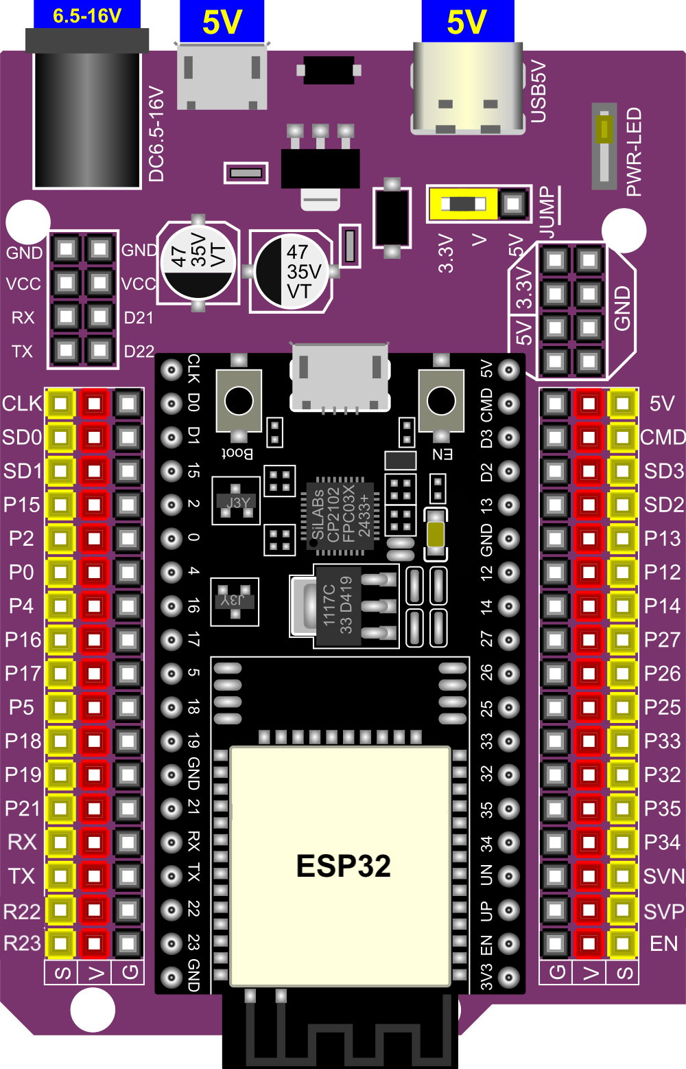
 Design with ESP32 38-pin Expansion Board in Cirkit Designer
Introduction
The ESP32 38-pin Expansion Board, manufactured by Espressif (Part ID: ESP32), is a versatile development board designed to simplify prototyping and development with the ESP32 microcontroller. Featuring 38 GPIO pins, this board provides seamless connectivity to a wide range of sensors, modules, and peripherals, making it ideal for Internet of Things (IoT) applications, smart devices, and embedded systems.
Explore Projects Built with ESP32 38-pin Expansion Board
 Open Project in Cirkit Designer
 Open Project in Cirkit Designer
 Open Project in Cirkit Designer
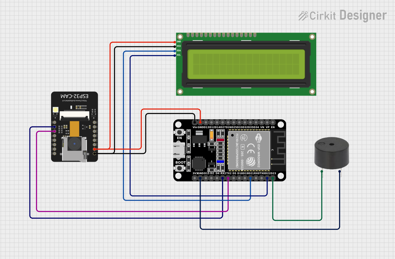 Open Project in Cirkit Designer
Explore Projects Built with ESP32 38-pin Expansion Board
Open Project in Cirkit DesignerOpen Project in Cirkit DesignerOpen Project in Cirkit DesignerOpen Project in Cirkit DesignerCommon Applications and Use Cases
- IoT devices and smart home automation
- Wireless communication projects (Wi-Fi and Bluetooth)
- Sensor data acquisition and processing
- Robotics and motor control
- Prototyping and educational projects
Technical Specifications
The ESP32 38-pin Expansion Board is built to support the powerful ESP32 microcontroller, offering robust performance and connectivity options. Below are the key technical details:
Key Technical Details
| Parameter | Specification |
|---|---|
| Microcontroller | ESP32 (dual-core, 32-bit Xtensa LX6) |
| Operating Voltage | 3.3V |
| Input Voltage Range | 5V (via USB) |
| GPIO Pins | 38 |
| Wi-Fi Standard | 802.11 b/g/n |
| Bluetooth Standard | Bluetooth 4.2 (Classic + BLE) |
| Flash Memory | 4MB |
| SRAM | 520KB |
| Clock Speed | Up to 240 MHz |
| Interfaces | UART, SPI, I2C, I2S, PWM, ADC, DAC |
| ADC Channels | 18 (12-bit resolution) |
| DAC Channels | 2 |
| USB Interface | Micro-USB |
| Dimensions | 54mm x 25mm |
Pin Configuration and Descriptions
The ESP32 38-pin Expansion Board features a total of 38 GPIO pins, each with specific functions. Below is the pinout description:
| Pin Number | Pin Name | Functionality |
|---|---|---|
| 1 | EN | Enable pin (active high) |
| 2 | IO0 | GPIO0, boot mode selection |
| 3 | IO1 (TX0) | GPIO1, UART0 TX |
| 4 | IO3 (RX0) | GPIO3, UART0 RX |
| 5 | IO4 | GPIO4, PWM, ADC1_CH0 |
| 6 | IO5 | GPIO5, PWM, ADC1_CH1 |
| ... | ... | ... (Refer to the full datasheet) |
| 38 | GND | Ground |
Note: Some pins have multiple functions (e.g., ADC, PWM, UART). Refer to the ESP32 datasheet for detailed pin multiplexing information.
Usage Instructions
How to Use the Component in a Circuit
Powering the Board:
- Connect the board to a computer or USB power source using a Micro-USB cable. The onboard voltage regulator ensures the ESP32 operates at 3.3V.
Connecting Peripherals:
- Use jumper wires to connect sensors, actuators, or other modules to the GPIO pins. Ensure the voltage levels of connected devices are compatible with the ESP32 (3.3V logic).
Programming the ESP32:
- Install the Arduino IDE or Espressif's ESP-IDF development environment.
- Add the ESP32 board support package to the Arduino IDE via the Boards Manager.
- Select the correct board ("ESP32 Dev Module") and port in the IDE settings.
Uploading Code:
- Write or load a program in the IDE and upload it to the ESP32 via the Micro-USB connection. The onboard boot and reset buttons can be used to assist with programming.
Important Considerations and Best Practices
- Voltage Levels: Avoid connecting 5V logic devices directly to the GPIO pins. Use level shifters if necessary.
- Pin Multiplexing: Some pins serve multiple functions (e.g., ADC, UART). Configure the pins appropriately in your code.
- Power Supply: Ensure the USB power source provides sufficient current (at least 500mA) for stable operation.
- Wi-Fi and Bluetooth: Avoid placing the board in metal enclosures, as this may interfere with wireless communication.
Example Code for Arduino UNO Integration
Below is an example of using the ESP32 to read data from a DHT11 temperature and humidity sensor:
#include <WiFi.h>
#include <DHT.h>

// Define DHT sensor type and pin
#define DHTPIN 4       // GPIO4 connected to DHT11 data pin
#define DHTTYPE DHT11  // DHT11 sensor

DHT dht(DHTPIN, DHTTYPE);

void setup() {
  Serial.begin(115200);  // Initialize serial communication
  dht.begin();           // Initialize the DHT sensor
  Serial.println("DHT11 Sensor Test");
}

void loop() {
  delay(2000);  // Wait 2 seconds between readings

  // Read temperature and humidity
  float humidity = dht.readHumidity();
  float temperature = dht.readTemperature();

  // Check if readings are valid
  if (isnan(humidity) || isnan(temperature)) {
    Serial.println("Failed to read from DHT sensor!");
    return;
  }

  // Print readings to the Serial Monitor
  Serial.print("Humidity: ");
  Serial.print(humidity);
  Serial.print("%  Temperature: ");
  Serial.print(temperature);
  Serial.println("°C");
}
Note: Ensure the DHT11 sensor is connected to GPIO4 and powered with 3.3V.
Troubleshooting and FAQs
Common Issues Users Might Face
ESP32 Not Detected by Computer:
- Ensure the USB cable is functional and supports data transfer.
- Install the correct USB-to-serial driver for your operating system.
Code Upload Fails:
- Check that the correct board and port are selected in the IDE.
- Press and hold the "BOOT" button while uploading the code.
Wi-Fi Connection Issues:
- Verify the SSID and password in your code.
- Ensure the router is within range and supports 2.4GHz Wi-Fi.
GPIO Pin Malfunction:
- Confirm that the pin is not being used for another function (e.g., ADC, UART).
- Avoid exceeding the maximum current rating of the GPIO pins (12mA).
Solutions and Tips for Troubleshooting
- Use a multimeter to check power supply voltage and continuity of connections.
- Refer to the ESP32 datasheet for detailed pinout and electrical characteristics.
- Update the ESP32 board package in the Arduino IDE to the latest version.
By following this documentation, users can effectively utilize the ESP32 38-pin Expansion Board for a wide range of applications, from simple prototypes to advanced IoT systems.