A thin film pressure sensor is a highly sensitive electronic component designed to measure pressure by detecting changes in resistance or capacitance within a thin film material. These sensors are compact, lightweight, and versatile, making them ideal for applications where space and precision are critical.
Explore Projects Built with thin film pressure sensor
Use Cirkit Designer to design, explore, and prototype these projects online. Some projects support real-time simulation. Click "Open Project" to start designing instantly!
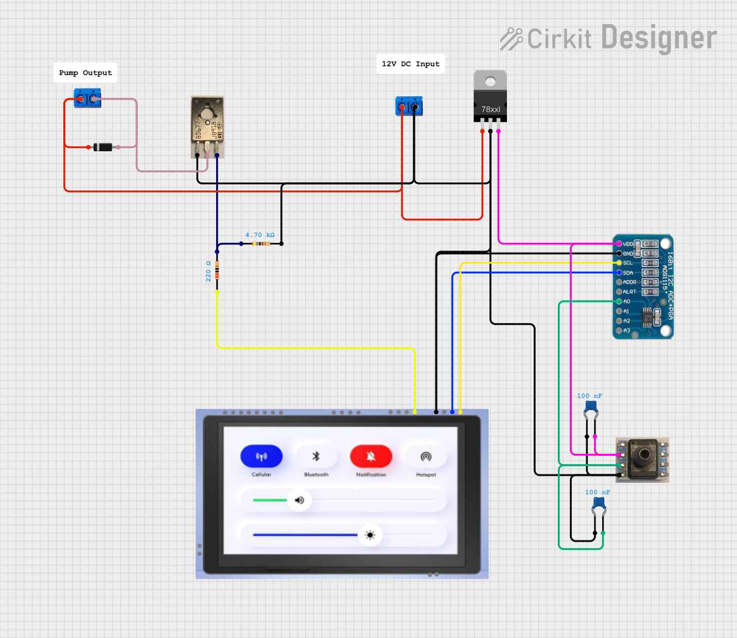
This circuit is designed to measure pressure using a transducer, convert the analog signal to digital with an ADS1115 ADC, and process and display the data on an ESP32 microcontroller with a 7-inch screen. It includes power regulation and filtering, as well as a Darlington transistor for load control.
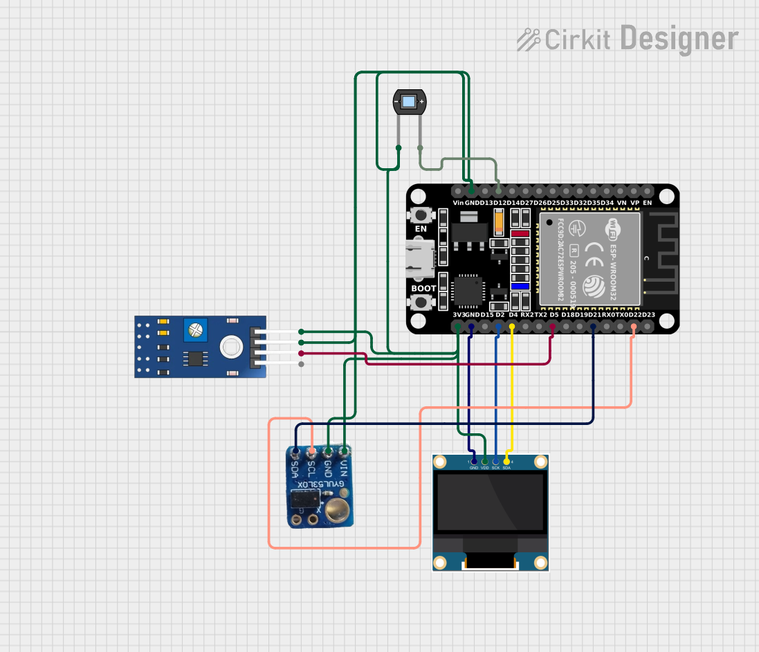
This circuit is designed to monitor eye pressure and deformation using a photodiode, a TCRT 5000 IR sensor, and a VL53L0X time-of-flight distance sensor. The ESP32 microcontroller reads sensor data, processes it to determine eye pressure status, and displays the results on a 0.96" OLED screen. It includes safety features, sensor calibration, and the ability to display sensor values and eye pressure status in real-time.
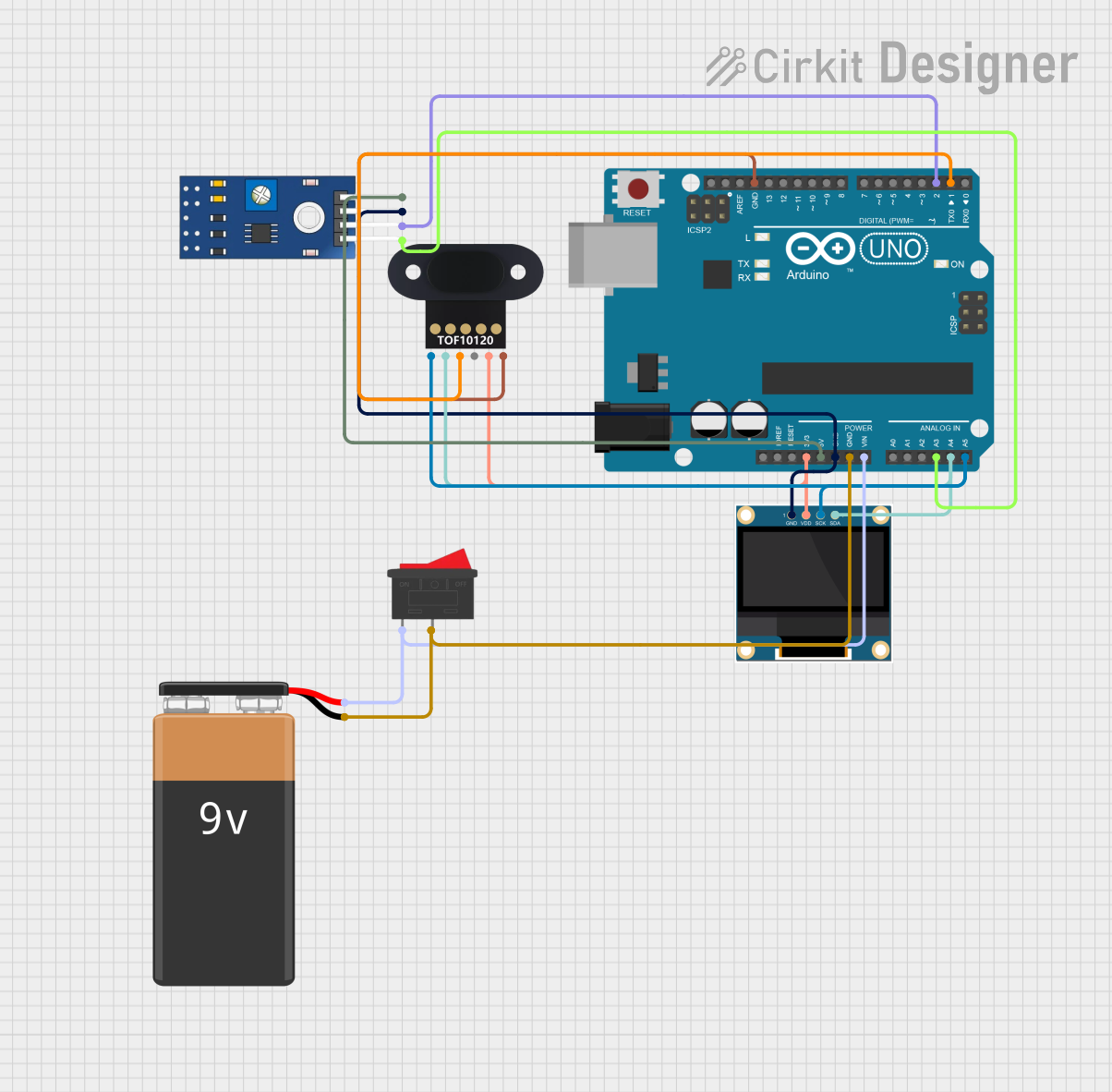
This circuit is designed to measure eye pressure and display the status on a 0.96" OLED screen, using an Arduino UNO as the central processing unit. It includes a TOF10120 sensor for distance measurement and a TCRT 5000 IR sensor for detecting surface changes, both interfacing with the Arduino. A 9V battery powers the system, with a rocker switch to control power flow, and the Arduino manages sensor data processing and OLED display output to indicate eye pressure as high, normal, or low.
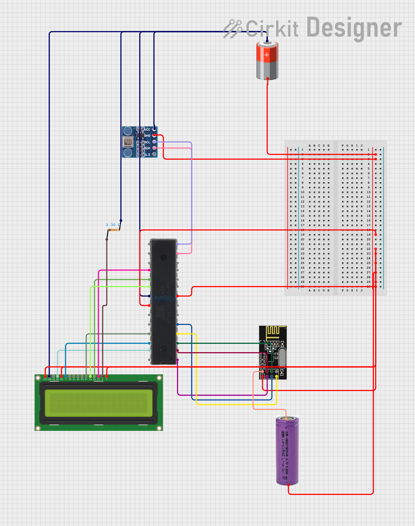
This circuit is designed for a Tire Pressure Monitoring System using an ATmega328P microcontroller. It reads temperature and pressure data from BMP180 sensors, displays the readings on a 16x2 LCD, and transmits the data wirelessly via an NRF24L01 module. The circuit is powered by a 5V battery, with a 3.3V battery specifically for the NRF24L01, and includes a resistor for the LCD backlight.
Medical Devices: Used in devices like blood pressure monitors and respiratory equipment.
Industrial Equipment: Employed in robotics, automation systems, and pressure monitoring tools.
Consumer Electronics: Integrated into touch-sensitive devices and wearable technology.
Automotive Systems: Used for tire pressure monitoring and seat occupancy detection.
Technical Specifications
Below are the general technical specifications for a typical thin film pressure sensor. Note that specific values may vary depending on the manufacturer and model.
Key Technical Details
Operating Voltage: 3.3V to 5V
Operating Current: < 10mA
Pressure Range: 0 to 10 bar (varies by model)
Output Type: Analog (resistance or voltage change)
Response Time: < 1ms
Operating Temperature: -20°C to 85°C
Durability: Up to 1 million pressure cycles
Pin Configuration and Descriptions
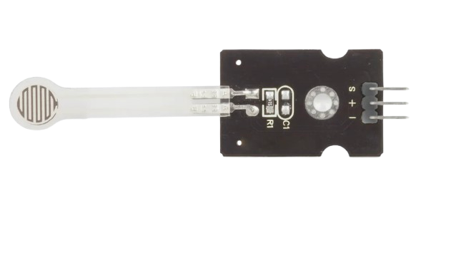
The thin film pressure sensor typically has a 2-pin or 3-pin configuration. Below is a table describing the pinout for a common 3-pin model:
Pin
Name
Description
1
VCC
Power supply input (3.3V to 5V). Connect to the positive terminal of the power source.
2
GND
Ground connection. Connect to the negative terminal of the power source.
3
Signal Output
Analog output signal proportional to the applied pressure.
For 2-pin models, the pins are typically:
Pin 1: Signal and power input (combined)
Pin 2: Ground
Usage Instructions
How to Use the Component in a Circuit
Power the Sensor: Connect the VCC pin to a 3.3V or 5V power source and the GND pin to ground.
Read the Output: Connect the Signal Output pin to an analog input pin of a microcontroller (e.g., Arduino UNO) or an analog-to-digital converter (ADC).
Calibrate the Sensor: Apply known pressure values to the sensor and record the corresponding output to create a calibration curve.
Implement in Circuit: Use the sensor in your application circuit, ensuring proper placement to avoid mechanical stress or damage.
Important Considerations and Best Practices
Avoid Overloading: Do not exceed the sensor's maximum pressure rating to prevent damage.
Stable Power Supply: Use a regulated power source to ensure accurate readings.
Environmental Protection: If used in harsh environments, protect the sensor from moisture, dust, and extreme temperatures.
Calibration: Regularly calibrate the sensor for consistent performance, especially in critical applications.
Example: Connecting to an Arduino UNO
Below is an example of how to connect and read data from a thin film pressure sensor using an Arduino UNO.
Circuit Diagram
VCC: Connect to the Arduino's 5V pin.
GND: Connect to the Arduino's GND pin.
Signal Output: Connect to an analog input pin (e.g., A0).
Arduino Code
// Define the analog pin connected to the sensor
const int sensorPin = A0;

// Variable to store the sensor reading
int sensorValue = 0;

void setup() {
  // Initialize serial communication for debugging
  Serial.begin(9600);
}

void loop() {
  // Read the analog value from the sensor
  sensorValue = analogRead(sensorPin);

  // Convert the analog value to a voltage (assuming 5V reference)
  float voltage = sensorValue * (5.0 / 1023.0);

  // Print the sensor value and voltage to the Serial Monitor
  Serial.print("Sensor Value: ");
  Serial.print(sensorValue);
  Serial.print(" | Voltage: ");
  Serial.println(voltage);

  // Add a small delay for stability
  delay(500);
}
Troubleshooting and FAQs
Common Issues and Solutions
No Output Signal
Cause: Incorrect wiring or power supply.
Solution: Double-check the connections and ensure the power supply is within the specified range.
Inconsistent Readings
Cause: Electrical noise or unstable power supply.
Solution: Use decoupling capacitors near the sensor and ensure a stable power source.
Sensor Not Responding to Pressure
Cause: Sensor damage or improper placement.
Solution: Inspect the sensor for physical damage and ensure it is properly mounted.
Output Signal Saturates
Cause: Pressure exceeds the sensor's maximum range.
Solution: Ensure the applied pressure is within the specified range.
FAQs
Q: Can the sensor measure negative pressure (vacuum)?
A: Some models are designed to measure both positive and negative pressures. Check the datasheet for details.
Q: How do I protect the sensor in a wet environment?
A: Use a waterproof enclosure or apply a conformal coating to shield the sensor.
Q: Can I use this sensor with a 3.3V microcontroller?
A: Yes, as long as the sensor's operating voltage range includes 3.3V.
Q: How do I improve the accuracy of the sensor?
A: Regularly calibrate the sensor, use a stable power supply, and minimize environmental noise.
This documentation provides a comprehensive guide to understanding, using, and troubleshooting thin film pressure sensors. For specific details, always refer to the manufacturer's datasheet.

 Open Project in Cirkit Designer