How to Use SMPS PSU 12V 10A: Examples, Pinouts, and Specs
Introduction
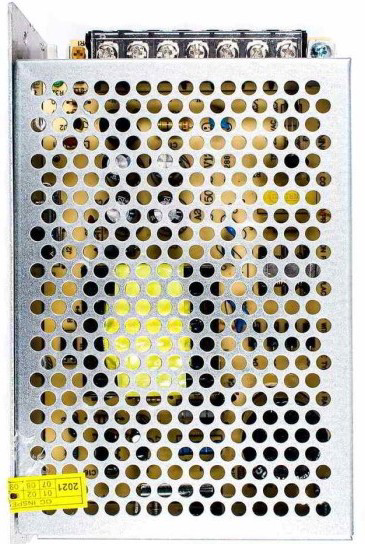
The SMPS PSU 12V 10A is a Switch Mode Power Supply designed to efficiently convert AC mains voltage into a stable DC output of 12 volts with a maximum current capacity of 10 amps. This component is widely used in applications requiring reliable and high-current DC power, such as LED lighting systems, industrial automation, CCTV systems, and powering microcontroller-based projects.
Switch Mode Power Supplies are known for their high efficiency, compact size, and ability to handle varying input voltages, making them ideal for both commercial and hobbyist applications.
Explore Projects Built with SMPS PSU 12V 10A


Explore Projects Built with SMPS PSU 12V 10A
Technical Specifications
Below are the key technical details of the SMPS PSU 12V 10A:
| Parameter | Specification |
|---|---|
| Input Voltage Range | 100-240V AC, 50/60Hz |
| Output Voltage | 12V DC |
| Maximum Output Current | 10A |
| Output Power | 120W |
| Efficiency | ≥85% |
| Ripple and Noise | ≤120mV |
| Operating Temperature | -10°C to +50°C |
| Cooling Method | Natural air cooling or fan-assisted |
| Protection Features | Overload, overvoltage, short circuit |
Pin Configuration and Descriptions
The SMPS PSU 12V 10A typically has the following terminal connections:
| Pin Label | Description |
|---|---|
| L | Live AC input (mains voltage) |
| N | Neutral AC input (mains voltage) |
| GND | Ground connection for safety |
| V+ | Positive DC output (12V) |
| V- | Negative DC output (ground for 12V output) |
Usage Instructions
How to Use the SMPS PSU 12V 10A in a Circuit
- Safety First: Ensure the SMPS is disconnected from the mains power before wiring. Use insulated tools and follow proper safety precautions when working with high-voltage AC inputs.
- Connect the AC Input:
- Connect the
Lterminal to the live wire of the AC mains. - Connect the
Nterminal to the neutral wire of the AC mains. - Optionally, connect the
GNDterminal to the earth ground for safety.
- Connect the
- Connect the DC Output:
- Connect the
V+terminal to the positive input of your load or circuit. - Connect the
V-terminal to the ground or negative input of your load or circuit.
- Connect the
- Power On: After verifying all connections, plug the SMPS into the mains power and switch it on. The output should provide a stable 12V DC.
Important Considerations and Best Practices
- Load Requirements: Ensure the total current draw of your connected devices does not exceed 10A to avoid overloading the SMPS.
- Ventilation: Place the SMPS in a well-ventilated area to prevent overheating. Avoid enclosing it in tight spaces without airflow.
- Polarity: Double-check the polarity of the DC output connections to prevent damage to your devices.
- Fuse Protection: Consider adding a fuse on the AC input side for additional protection against surges or faults.
- Arduino Compatibility: The SMPS can be used to power Arduino projects. Use a voltage regulator or step-down module if your Arduino board requires a lower voltage (e.g., 5V).
Example: Powering an Arduino UNO
To power an Arduino UNO using the SMPS PSU 12V 10A:
- Connect the
V+terminal of the SMPS to the VIN pin of the Arduino UNO. - Connect the
V-terminal of the SMPS to the GND pin of the Arduino UNO. - Ensure the Arduino's onboard voltage regulator is functioning properly to step down the 12V to 5V for internal use.
Here is a simple Arduino sketch to blink an LED while powered by the SMPS:
// This sketch blinks an LED connected to pin 13 of the Arduino UNO.
// Ensure the SMPS is properly connected to the Arduino's VIN and GND pins.

void setup() {
  pinMode(13, OUTPUT); // Set pin 13 as an output pin
}

void loop() {
  digitalWrite(13, HIGH); // Turn the LED on
  delay(1000);            // Wait for 1 second
  digitalWrite(13, LOW);  // Turn the LED off
  delay(1000);            // Wait for 1 second
}
Troubleshooting and FAQs
Common Issues and Solutions
No Output Voltage:
- Check if the SMPS is properly connected to the AC mains.
- Verify that the input voltage is within the specified range (100-240V AC).
- Inspect the fuse (if present) and replace it if blown.
Overheating:
- Ensure the SMPS is not overloaded. Reduce the load if necessary.
- Check for proper ventilation and ensure the cooling fan (if present) is operational.
Output Voltage Fluctuations:
- Verify that the load does not exceed the maximum current rating (10A).
- Check for loose or faulty connections on the input and output terminals.
Noise or Ripple in Output:
- Add a capacitor (e.g., 1000µF) across the output terminals to reduce noise.
- Ensure the SMPS is not operating near its maximum load capacity.
FAQs
Q: Can I use this SMPS to power a 5V device?
A: No, the SMPS provides a fixed 12V output. To power a 5V device, use a step-down voltage regulator or DC-DC converter.
Q: Is the SMPS suitable for outdoor use?
A: Most SMPS units are not weatherproof. If outdoor use is required, ensure the SMPS is housed in a waterproof enclosure.
Q: What happens if I exceed the 10A current limit?
A: The SMPS is equipped with overload protection and will shut down or reduce output to prevent damage. Reduce the load to restore normal operation.
Q: Can I use this SMPS to charge a 12V battery?
A: While possible, it is not recommended unless the SMPS has a built-in charging circuit. Use a dedicated battery charger for optimal performance and safety.