How to Use Op-Amp: Examples, Pinouts, and Specs
Introduction
The OPA548 is a high-power operational amplifier (Op-Amp) manufactured by Texas Instruments. It is a versatile, high-gain voltage amplifier with differential inputs and a single-ended output. The OPA548 is designed to handle high current loads, making it suitable for driving motors, actuators, and other power-demanding applications. Its robust design and thermal protection features make it ideal for industrial, automotive, and audio applications.
Explore Projects Built with Op-Amp
Explore Projects Built with Op-Amp
Common Applications and Use Cases
- Motor control and servo systems
- Audio amplification
- Power supply regulation
- Signal conditioning and processing
- Test and measurement equipment
- Active filters and integrators
Technical Specifications
The OPA548 is a high-performance operational amplifier with the following key specifications:
| Parameter | Value |
|---|---|
| Supply Voltage Range | ±4V to ±30V or 8V to 60V |
| Output Current | Up to 3A |
| Slew Rate | 10V/µs |
| Gain Bandwidth Product | 1 MHz |
| Input Offset Voltage | ±2 mV (typical) |
| Quiescent Current | 15 mA (typical) |
| Thermal Shutdown Protection | Yes |
| Package Options | TO-220, DDPAK/TO-263 |
Pin Configuration and Descriptions
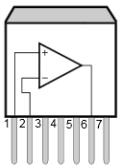
The OPA548 is available in a TO-220 package. Below is the pinout and description:
| Pin Number | Pin Name | Description |
|---|---|---|
| 1 | E/S | Enable/Shutdown pin. Used to enable or disable the amplifier. |
| 2 | -IN | Inverting input of the Op-Amp. |
| 3 | +IN | Non-inverting input of the Op-Amp. |
| 4 | V- | Negative power supply voltage. |
| 5 | OUT | Output of the Op-Amp. |
| 6 | V+ | Positive power supply voltage. |
| 7 | ILIM | Current limit adjustment pin. Used to set the maximum output current. |
| Tab | V- | Connected to the negative power supply voltage for heat dissipation purposes. |
Usage Instructions
How to Use the OPA548 in a Circuit
- Power Supply: Connect the OPA548 to a dual power supply (e.g., ±15V) or a single power supply (e.g., 24V). Ensure the supply voltage is within the specified range (±4V to ±30V or 8V to 60V).
- Input Connections: Connect the signal source to the inverting (-IN) or non-inverting (+IN) input, depending on the desired configuration (e.g., inverting or non-inverting amplifier).
- Output Load: Connect the load to the output pin (OUT). Ensure the load does not exceed the maximum output current of 3A.
- Current Limiting: Use the ILIM pin to set the current limit. Connect a resistor between ILIM and V- to adjust the current limit. Refer to the datasheet for resistor values corresponding to specific current limits.
- Enable/Shutdown: Use the E/S pin to enable or disable the amplifier. Pull the pin high to enable the amplifier or low to disable it.
Important Considerations and Best Practices
- Thermal Management: The OPA548 can dissipate significant power. Use a heatsink or proper PCB design to manage heat dissipation.
- Decoupling Capacitors: Place decoupling capacitors (e.g., 0.1 µF and 10 µF) close to the power supply pins to reduce noise and improve stability.
- Stability: For capacitive loads, use a small resistor (e.g., 10Ω) in series with the output to ensure stability.
- Current Limiting: Always set the current limit to protect the amplifier and the load from damage.
Example: Using OPA548 with Arduino UNO
The OPA548 can be used with an Arduino UNO to amplify an analog signal. Below is an example of a simple non-inverting amplifier circuit:
Circuit Connections
- Connect the Arduino's analog output (e.g., pin A0) to the +IN pin of the OPA548.
- Connect a resistor (R1) between the -IN pin and ground.
- Connect another resistor (R2) between the -IN pin and the output (OUT) pin of the OPA548.
- Connect the load to the OUT pin.
- Set the gain of the amplifier using the formula: Gain = 1 + (R2 / R1).
Arduino Code
// Example code to generate an analog signal from Arduino UNO
// This signal can be amplified using the OPA548 in a non-inverting configuration.

void setup() {
  // Initialize pin A0 as an analog output
  pinMode(A0, OUTPUT);
}

void loop() {
  // Generate a sine wave signal on pin A0
  for (int i = 0; i < 360; i++) {
    // Calculate the sine wave value (scaled to 0-255 for PWM output)
    int value = 127 + 127 * sin(i * DEG_TO_RAD);
    analogWrite(A0, value); // Output the signal
    delay(10); // Delay to control the frequency of the signal
  }
}
Troubleshooting and FAQs
Common Issues and Solutions
Amplifier Overheating
- Cause: Excessive power dissipation or insufficient thermal management.
- Solution: Use a heatsink or improve PCB thermal design. Ensure the load current is within the specified limit.
Output Signal Distortion
- Cause: Incorrect gain settings or unstable circuit.
- Solution: Verify resistor values for the desired gain. Add a compensation capacitor if necessary.
No Output Signal
- Cause: E/S pin is not properly configured or power supply is disconnected.
- Solution: Ensure the E/S pin is pulled high to enable the amplifier. Check power supply connections.
Current Limiting Not Working
- Cause: Incorrect resistor value on the ILIM pin.
- Solution: Verify the resistor value and refer to the datasheet for proper configuration.
FAQs
Q1: Can the OPA548 drive capacitive loads?
A1: Yes, but for large capacitive loads, use a small resistor (e.g., 10Ω) in series with the output to ensure stability.
Q2: What is the maximum output current of the OPA548?
A2: The OPA548 can deliver up to 3A of output current.
Q3: How do I set the current limit?
A3: Connect a resistor between the ILIM pin and V-. The resistor value determines the current limit. Refer to the datasheet for details.
Q4: Is the OPA548 protected against thermal overload?
A4: Yes, the OPA548 includes thermal shutdown protection to prevent damage from overheating.