How to Use PCB Mobkits V4: Examples, Pinouts, and Specs
Introduction
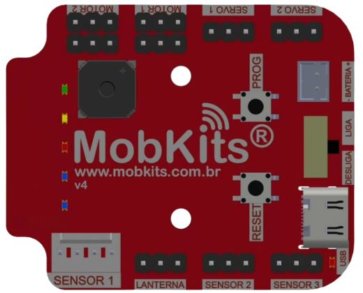
The PCB Mobkits V4 is a versatile printed circuit board (PCB) designed by Mobkits to simplify prototyping and building electronic projects. It features a well-organized layout with multiple mounting options, making it suitable for a wide range of applications. The PCB is equipped with connectivity for various components, including sensors, microcontrollers, and power modules, enabling users to create robust and efficient circuits with ease.
Explore Projects Built with PCB Mobkits V4


Explore Projects Built with PCB Mobkits V4
Common Applications and Use Cases
- Rapid prototyping of electronic circuits
- Building custom IoT devices
- Educational projects for learning circuit design
- Integration with microcontrollers like Arduino, ESP32, and Raspberry Pi
- DIY robotics and automation systems
Technical Specifications
The PCB Mobkits V4 is designed to provide flexibility and ease of use for both beginners and experienced users. Below are the key technical details:
General Specifications
- Dimensions: 100mm x 70mm
- Material: FR4 (Flame Retardant 4) with 1.6mm thickness
- Copper Layer: Double-sided, 1oz copper
- Solder Mask: Green with white silkscreen
- Operating Voltage: Up to 24V DC
- Maximum Current: 2A per trace (recommended)
- Mounting Holes: 4 holes, 3mm diameter, spaced for standard enclosures
Pin Configuration and Descriptions
The PCB includes multiple headers and connectors for easy integration with components. Below is a detailed description of the pin layout:
Power Input Section
| Pin Label | Description | Voltage Range | Notes |
|---|---|---|---|
| VIN | Main power input | 5V - 24V DC | Connect to external power source |
| GND | Ground connection | 0V | Common ground for the circuit |
Microcontroller Interface
| Pin Label | Description | Voltage Level | Notes |
|---|---|---|---|
| 5V | Regulated 5V output | 5V DC | For powering external modules |
| 3.3V | Regulated 3.3V output | 3.3V DC | For low-voltage components |
| IO1-IO8 | General-purpose I/O pins | 0V - 5V | Connect to sensors or actuators |
Additional Features
| Feature | Description |
|---|---|
| Breadboard Area | Includes a prototyping area with 0.1-inch pitch holes |
| Screw Terminals | For secure power and signal connections |
| LED Indicators | Power and status LEDs for quick diagnostics |
Usage Instructions
The PCB Mobkits V4 is designed for ease of use, even for beginners. Follow the steps below to use the PCB effectively in your projects:
Step 1: Powering the PCB
- Connect a DC power source (5V to 24V) to the VIN and GND terminals.
- Ensure the power source matches the voltage requirements of your components.
Step 2: Connecting Components
- Use the IO1-IO8 pins to connect sensors, actuators, or other peripherals.
- For low-power components, use the 3.3V or 5V regulated outputs.
- Secure connections using the screw terminals or solder components directly to the prototyping area.
Step 3: Integrating with a Microcontroller
- Mount your microcontroller (e.g., Arduino UNO) onto the PCB using the provided headers.
- Connect the microcontroller's pins to the corresponding IO pins on the PCB.
- Use jumper wires or solder connections for additional flexibility.
Example: Using PCB Mobkits V4 with Arduino UNO
Below is an example of how to blink an LED connected to the PCB using an Arduino UNO:
// Define the pin connected to the LED
const int ledPin = 7; // Connect the LED to IO7 on the PCB

void setup() {
  pinMode(ledPin, OUTPUT); // Set the LED pin as an output
}

void loop() {
  digitalWrite(ledPin, HIGH); // Turn the LED on
  delay(1000);                // Wait for 1 second
  digitalWrite(ledPin, LOW);  // Turn the LED off
  delay(1000);                // Wait for 1 second
}
Best Practices
- Use appropriate wire gauges for power connections to avoid overheating.
- Verify all connections before powering the circuit to prevent short circuits.
- Use the onboard prototyping area for custom circuits and additional components.
Troubleshooting and FAQs
Common Issues and Solutions
No Power to the PCB
- Cause: Incorrect power source or loose connections.
- Solution: Verify the power source voltage and ensure secure connections to VIN and GND.
Microcontroller Not Responding
- Cause: Incorrect pin connections or insufficient power.
- Solution: Double-check the pin mappings and ensure the microcontroller is receiving adequate power.
LED Indicators Not Working
- Cause: Faulty components or incorrect polarity.
- Solution: Inspect the LED connections and replace any damaged components.
Overheating Traces
- Cause: Excessive current through PCB traces.
- Solution: Ensure the current does not exceed 2A per trace. Use external wiring for high-current applications.
FAQs
Q1: Can I use the PCB Mobkits V4 with a Raspberry Pi?
A1: Yes, the PCB is compatible with Raspberry Pi. Use the 3.3V output for GPIO connections and ensure proper voltage levels.
Q2: Is the PCB suitable for high-frequency circuits?
A2: The PCB is primarily designed for prototyping and general-purpose use. For high-frequency circuits, additional shielding may be required.
Q3: Can I solder components directly to the PCB?
A3: Yes, the prototyping area is designed for soldering components directly.
Q4: What is the maximum power the PCB can handle?
A4: The PCB can handle up to 24V DC and 2A per trace. For higher power, use external wiring.
By following this documentation, you can effectively use the PCB Mobkits V4 to build and prototype your electronic projects with confidence.