Cirkit Designer Logo
Cirkit Designer
Your all-in-one circuit design IDE
Home / 
Component Documentation

How to Use Mtiny ESP32 WROVER-IE: Examples, Pinouts, and Specs

Image of Mtiny ESP32 WROVER-IE
Cirkit Designer LogoDesign with Mtiny ESP32 WROVER-IE in Cirkit Designer

Introduction

The Mtiny ESP32 WROVER-IE is a compact and powerful microcontroller board designed by Makerlabvn. It features the ESP32 WROVER-IE module, which is known for its combination of Wi-Fi, Bluetooth, and a rich set of peripherals. This board is ideal for a wide range of applications, including Internet of Things (IoT) devices, wearable electronics, smart home applications, and complex control systems.

Explore Projects Built with Mtiny ESP32 WROVER-IE
Use Cirkit Designer to design, explore, and prototype these projects online. Some projects support real-time simulation. Click "Open Project" to start designing instantly!
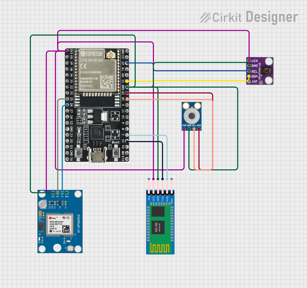
ESP32-Based Multi-Sensor Health Monitoring System with Bluetooth Connectivity
Image of circuit diagram: A project utilizing Mtiny ESP32 WROVER-IE in a practical application
This circuit features an ESP32-WROOM-32UE microcontroller as the central processing unit, interfacing with a variety of sensors and modules. It includes a MAX30100 pulse oximeter and heart-rate sensor, an MLX90614 infrared thermometer, an HC-05 Bluetooth module for wireless communication, and a Neo 6M GPS module for location tracking. All components are powered by a common voltage supply and are connected to specific GPIO pins on the ESP32 for data exchange, with the sensors using I2C communication and the modules using UART.
Cirkit Designer LogoOpen Project in Cirkit Designer
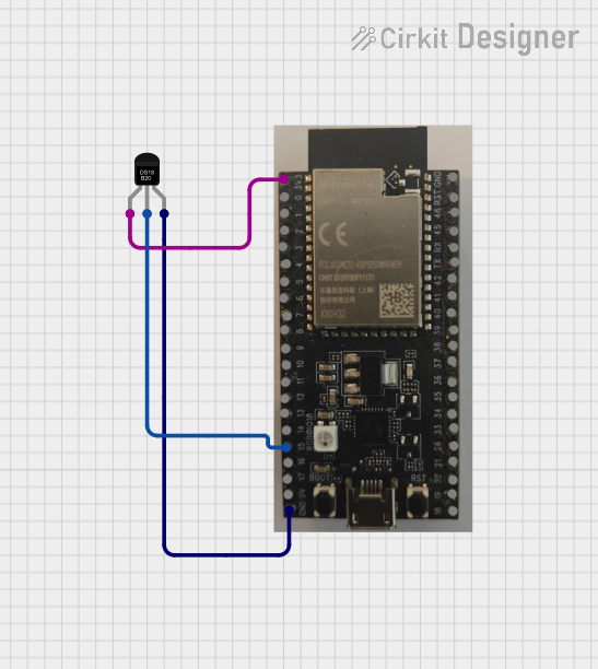
ESP32-S2-WROVER and DS18B20 Temperature Monitoring System
Image of Temperature: A project utilizing Mtiny ESP32 WROVER-IE in a practical application
This circuit features an ESP32-S2-WROVER microcontroller connected to a DS18B20 temperature sensor. The ESP32-S2-WROVER reads temperature data from the DS18B20 sensor via GPIO 15 and prints the temperature readings to the Serial Monitor.
Cirkit Designer LogoOpen Project in Cirkit Designer
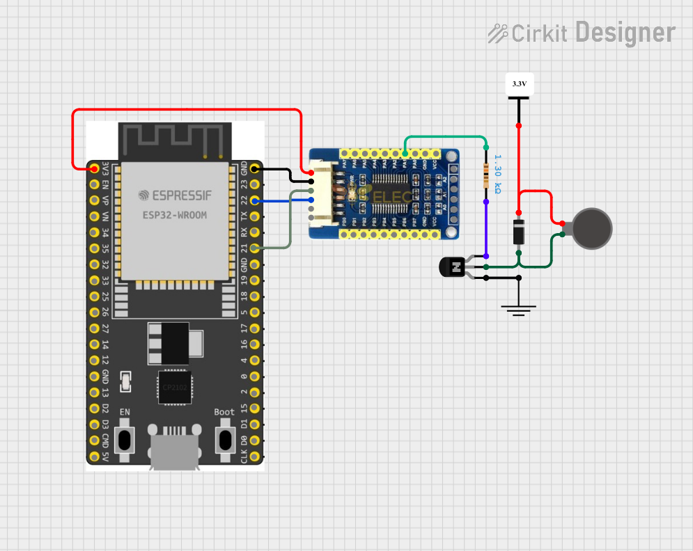
ESP32-Based Vibration Motor Controller with I2C IO Expansion
Image of VIBRATYION: A project utilizing Mtiny ESP32 WROVER-IE in a practical application
This circuit features an ESP32 Wroom Dev Kit microcontroller interfaced with an MCP23017 I/O expansion board via I2C communication, utilizing GPIO 21 and GPIO 22 for SDA and SCL lines, respectively. A vibration motor is controlled by an NPN transistor acting as a switch, with a diode for back EMF protection and a resistor to limit base current. The ESP32 can control the motor by sending signals to the MCP23017, which then interfaces with the transistor to turn the motor on or off.
Cirkit Designer LogoOpen Project in Cirkit Designer
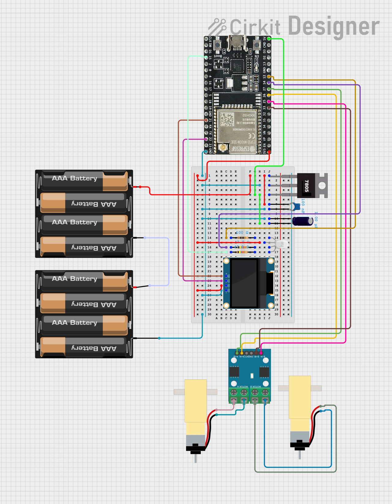
ESP32-WROOM-32UE Wi-Fi Controlled Robotic Car with OLED Display and RGB LED
Image of mkrl bot: A project utilizing Mtiny ESP32 WROVER-IE in a practical application
This circuit is a WiFi-controlled robotic system powered by an ESP32 microcontroller. It features an OLED display for status messages, an RGB LED for visual feedback, and dual hobby gearmotors driven by an L9110 motor driver for movement. The system is powered by a 4 x AAA battery pack regulated to 5V using a 7805 voltage regulator.
Cirkit Designer LogoOpen Project in Cirkit Designer

Explore Projects Built with Mtiny ESP32 WROVER-IE

Use Cirkit Designer to design, explore, and prototype these projects online. Some projects support real-time simulation. Click "Open Project" to start designing instantly!
Image of circuit diagram: A project utilizing Mtiny ESP32 WROVER-IE in a practical application
ESP32-Based Multi-Sensor Health Monitoring System with Bluetooth Connectivity
This circuit features an ESP32-WROOM-32UE microcontroller as the central processing unit, interfacing with a variety of sensors and modules. It includes a MAX30100 pulse oximeter and heart-rate sensor, an MLX90614 infrared thermometer, an HC-05 Bluetooth module for wireless communication, and a Neo 6M GPS module for location tracking. All components are powered by a common voltage supply and are connected to specific GPIO pins on the ESP32 for data exchange, with the sensors using I2C communication and the modules using UART.
Cirkit Designer LogoOpen Project in Cirkit Designer
Image of Temperature: A project utilizing Mtiny ESP32 WROVER-IE in a practical application
ESP32-S2-WROVER and DS18B20 Temperature Monitoring System
This circuit features an ESP32-S2-WROVER microcontroller connected to a DS18B20 temperature sensor. The ESP32-S2-WROVER reads temperature data from the DS18B20 sensor via GPIO 15 and prints the temperature readings to the Serial Monitor.
Cirkit Designer LogoOpen Project in Cirkit Designer
Image of VIBRATYION: A project utilizing Mtiny ESP32 WROVER-IE in a practical application
ESP32-Based Vibration Motor Controller with I2C IO Expansion
This circuit features an ESP32 Wroom Dev Kit microcontroller interfaced with an MCP23017 I/O expansion board via I2C communication, utilizing GPIO 21 and GPIO 22 for SDA and SCL lines, respectively. A vibration motor is controlled by an NPN transistor acting as a switch, with a diode for back EMF protection and a resistor to limit base current. The ESP32 can control the motor by sending signals to the MCP23017, which then interfaces with the transistor to turn the motor on or off.
Cirkit Designer LogoOpen Project in Cirkit Designer
Image of mkrl bot: A project utilizing Mtiny ESP32 WROVER-IE in a practical application
ESP32-WROOM-32UE Wi-Fi Controlled Robotic Car with OLED Display and RGB LED
This circuit is a WiFi-controlled robotic system powered by an ESP32 microcontroller. It features an OLED display for status messages, an RGB LED for visual feedback, and dual hobby gearmotors driven by an L9110 motor driver for movement. The system is powered by a 4 x AAA battery pack regulated to 5V using a 7805 voltage regulator.
Cirkit Designer LogoOpen Project in Cirkit Designer

Technical Specifications

Key Technical Details

  • Microcontroller: ESP32-D0WD
  • Operating Voltage: 3.3V
  • Input Voltage: 5V via micro USB or Vin pin
  • Digital I/O Pins: 25
  • Analog Input Pins: 12 (ADC2 x 8, ADC1 x 4)
  • Flash Memory: 4MB (WROVER-IE module)
  • SRAM: 520 KB SRAM + 8MB PSRAM
  • Clock Speed: 240MHz
  • Wi-Fi: 802.11 b/g/n
  • Bluetooth: Bluetooth 4.2 BR/EDR and BLE standards
  • Operating Temperature: -40°C to +85°C

Pin Configuration and Descriptions

Pin Number Function Description
1 3.3V Power supply for the board
2 GND Ground
3-14 GPIO0 - GPIO11 General Purpose Input/Output Pins
15 ADC2_CH1 Analog to Digital Converter, Channel 1
16 ADC2_CH2 Analog to Digital Converter, Channel 2
... ... ...
25 VIN Voltage Input for the board

Note: This is a simplified representation. Please refer to the official pinout diagram for complete details.

Usage Instructions

Integrating with a Circuit

To use the Mtiny ESP32 WROVER-IE in a circuit:

  1. Powering the Board: Connect a 5V power supply to the micro USB port or Vin pin.
  2. Connecting I/O: Utilize the GPIO pins for interfacing with sensors, actuators, and other components.
  3. Programming: Use the micro USB port to connect the board to a computer for programming.

Best Practices

  • Ensure that the power supply is stable and within the specified voltage range.
  • Avoid exposing the board to temperatures outside the specified operating range.
  • Use proper ESD precautions when handling the board to prevent damage.

Example Code for Arduino UNO

#include <WiFi.h>

// Replace with your network credentials
const char* ssid = "your_SSID";
const char* password = "your_PASSWORD";

void setup() {
  Serial.begin(115200);
  
  // Connect to Wi-Fi
  WiFi.begin(ssid, password);
  while (WiFi.status() != WL_CONNECTED) {
    delay(500);
    Serial.println("Connecting to WiFi...");
  }
  Serial.println("Connected to WiFi");
}

void loop() {
  // Put your main code here, to run repeatedly:
}

Troubleshooting and FAQs

Common Issues

  • Board Not Powering On: Check the power supply and USB cable.
  • Cannot Upload Code: Ensure the correct board and port are selected in the IDE.
  • Wi-Fi Connection Issues: Verify network credentials and signal strength.

Solutions and Tips

  • Power Supply: Use a quality power supply and cable to ensure stable operation.
  • Driver Installation: Make sure the appropriate USB drivers are installed on your computer.
  • Signal Strength: Place the board closer to the router or use an external antenna if needed.

FAQs

Q: Can the Mtiny ESP32 WROVER-IE be used with the Arduino IDE? A: Yes, it is compatible with the Arduino IDE. Make sure to install the ESP32 board package.

Q: What is the maximum voltage that can be applied to the GPIO pins? A: The maximum voltage for the GPIO pins is 3.3V. Applying more can damage the board.

Q: How can I enable Bluetooth functionality? A: Bluetooth can be enabled using the BluetoothSerial.h library in the Arduino IDE.

For further assistance, please refer to the Makerlabvn support forums or contact technical support.