How to Use 4 channel relay module 5V JD-VCC: Examples, Pinouts, and Specs
Introduction
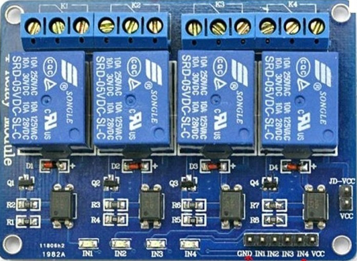
The 4-channel relay module (5V JD-VCC) is a versatile electronic component designed to control high-power devices using low-power control signals from a microcontroller, such as an Arduino or Raspberry Pi. This module features four independent relays, each capable of switching AC or DC loads. The JD-VCC pin allows for the isolation of the relay power supply from the control signal, improving safety and reducing electrical noise.
Explore Projects Built with 4 channel relay module 5V JD-VCC


Explore Projects Built with 4 channel relay module 5V JD-VCC
Common Applications and Use Cases
- Home automation systems (e.g., controlling lights, fans, or appliances)
- Industrial automation for switching motors or solenoids
- Robotics and IoT projects requiring high-power device control
- Smart energy management systems
Technical Specifications
Key Technical Details
- Operating Voltage (Control Logic): 5V DC
- Relay Voltage: 5V DC
- Trigger Voltage: Low-level trigger (0V to 2.5V)
- Relay Current (per channel): ~70mA
- Maximum Load (per relay):
- AC: 250V at 10A
- DC: 30V at 10A
- Isolation: Optocoupler-based isolation
- Dimensions: ~75mm x 55mm x 20mm
- Weight: ~60g
Pin Configuration and Descriptions
The module has two sets of pins: control pins and power pins. Additionally, each relay has three output terminals.
Control and Power Pins
| Pin Name | Description |
|---|---|
| IN1 | Control signal for Relay 1 (active LOW) |
| IN2 | Control signal for Relay 2 (active LOW) |
| IN3 | Control signal for Relay 3 (active LOW) |
| IN4 | Control signal for Relay 4 (active LOW) |
| GND | Ground connection for the control circuit |
| VCC | 5V power supply for the control circuit |
| JD-VCC | 5V power supply for the relay coils (isolated from VCC for safety and stability) |
| Jumper Cap | Connects VCC and JD-VCC for shared power supply (remove for separate supplies) |
Relay Output Terminals (per relay)
| Terminal | Description |
|---|---|
| NO (Normally Open) | Open circuit when the relay is inactive; closed when the relay is active |
| COM (Common) | Common terminal for the relay switch |
| NC (Normally Closed) | Closed circuit when the relay is inactive; open when the relay is active |
Usage Instructions
How to Use the Component in a Circuit
Powering the Module:
- Connect the JD-VCC pin to a 5V power supply for the relay coils.
- Connect the VCC pin to a 5V power supply for the control circuit.
- If you want to use a single power source for both, place the jumper cap between VCC and JD-VCC.
Connecting the Control Signals:
- Connect the IN1, IN2, IN3, and IN4 pins to the digital output pins of your microcontroller.
- Ensure the microcontroller shares a common ground (GND) with the relay module.
Connecting the Load:
- For each relay, connect the load to the COM and either the NO or NC terminal, depending on whether you want the load to be normally off or on.
Programming the Microcontroller:
- Use digitalWrite() commands to send LOW signals to activate the relays and HIGH signals to deactivate them.
Important Considerations and Best Practices
- Isolation: For safety, use a separate power supply for JD-VCC and VCC when controlling high-power loads.
- Flyback Diodes: Ensure the module has built-in flyback diodes to protect against voltage spikes. Most JD-VCC modules include this feature.
- Load Ratings: Do not exceed the maximum load ratings of the relays to avoid damage.
- Active LOW Trigger: Remember that the relays are triggered by a LOW signal (0V).
Example Code for Arduino UNO
// Example code to control a 4-channel relay module with Arduino UNO
// Ensure the relay module's GND is connected to the Arduino's GND

#define RELAY1 2  // Define pin 2 for Relay 1
#define RELAY2 3  // Define pin 3 for Relay 2
#define RELAY3 4  // Define pin 4 for Relay 3
#define RELAY4 5  // Define pin 5 for Relay 4

void setup() {
  // Set relay pins as outputs
  pinMode(RELAY1, OUTPUT);
  pinMode(RELAY2, OUTPUT);
  pinMode(RELAY3, OUTPUT);
  pinMode(RELAY4, OUTPUT);

  // Initialize all relays to OFF (HIGH state)
  digitalWrite(RELAY1, HIGH);
  digitalWrite(RELAY2, HIGH);
  digitalWrite(RELAY3, HIGH);
  digitalWrite(RELAY4, HIGH);
}

void loop() {
  // Example: Turn relays ON and OFF sequentially
  digitalWrite(RELAY1, LOW);  // Turn Relay 1 ON
  delay(1000);                // Wait for 1 second
  digitalWrite(RELAY1, HIGH); // Turn Relay 1 OFF

  digitalWrite(RELAY2, LOW);  // Turn Relay 2 ON
  delay(1000);                // Wait for 1 second
  digitalWrite(RELAY2, HIGH); // Turn Relay 2 OFF

  digitalWrite(RELAY3, LOW);  // Turn Relay 3 ON
  delay(1000);                // Wait for 1 second
  digitalWrite(RELAY3, HIGH); // Turn Relay 3 OFF

  digitalWrite(RELAY4, LOW);  // Turn Relay 4 ON
  delay(1000);                // Wait for 1 second
  digitalWrite(RELAY4, HIGH); // Turn Relay 4 OFF
}
Troubleshooting and FAQs
Common Issues and Solutions
Relays Not Activating:
- Ensure the JD-VCC and VCC pins are properly powered.
- Verify that the control signals (IN1–IN4) are set to LOW to activate the relays.
Electrical Noise or Interference:
- Use separate power supplies for JD-VCC and VCC to isolate the relay coils from the control circuit.
- Add capacitors across the power supply lines to filter noise.
Load Not Switching Properly:
- Check the wiring of the load to the relay terminals (COM, NO, NC).
- Ensure the load does not exceed the relay's maximum current and voltage ratings.
Microcontroller Resetting When Relays Activate:
- This may be caused by voltage spikes or insufficient power supply. Use a separate power source for JD-VCC and add a flyback diode if necessary.
FAQs
Can I use this module with a 3.3V microcontroller?
- Yes, but you may need a level shifter or transistor circuit to ensure proper triggering of the relays.
What happens if I remove the jumper cap?
- The JD-VCC and VCC pins will no longer be connected, allowing you to use separate power supplies for the relay coils and control circuit.
Is the module safe for high-power AC loads?
- Yes, but ensure proper insulation and follow safety guidelines when working with high-voltage AC loads.