Cirkit Designer Logo
Cirkit Designer
Your all-in-one circuit design IDE
Home / 
Component Documentation

How to Use SparkFun SSOP to DIP Adapter - 16-Pin: Examples, Pinouts, and Specs

Image of SparkFun SSOP to DIP Adapter - 16-Pin
Cirkit Designer LogoDesign with SparkFun SSOP to DIP Adapter - 16-Pin in Cirkit Designer

Introduction

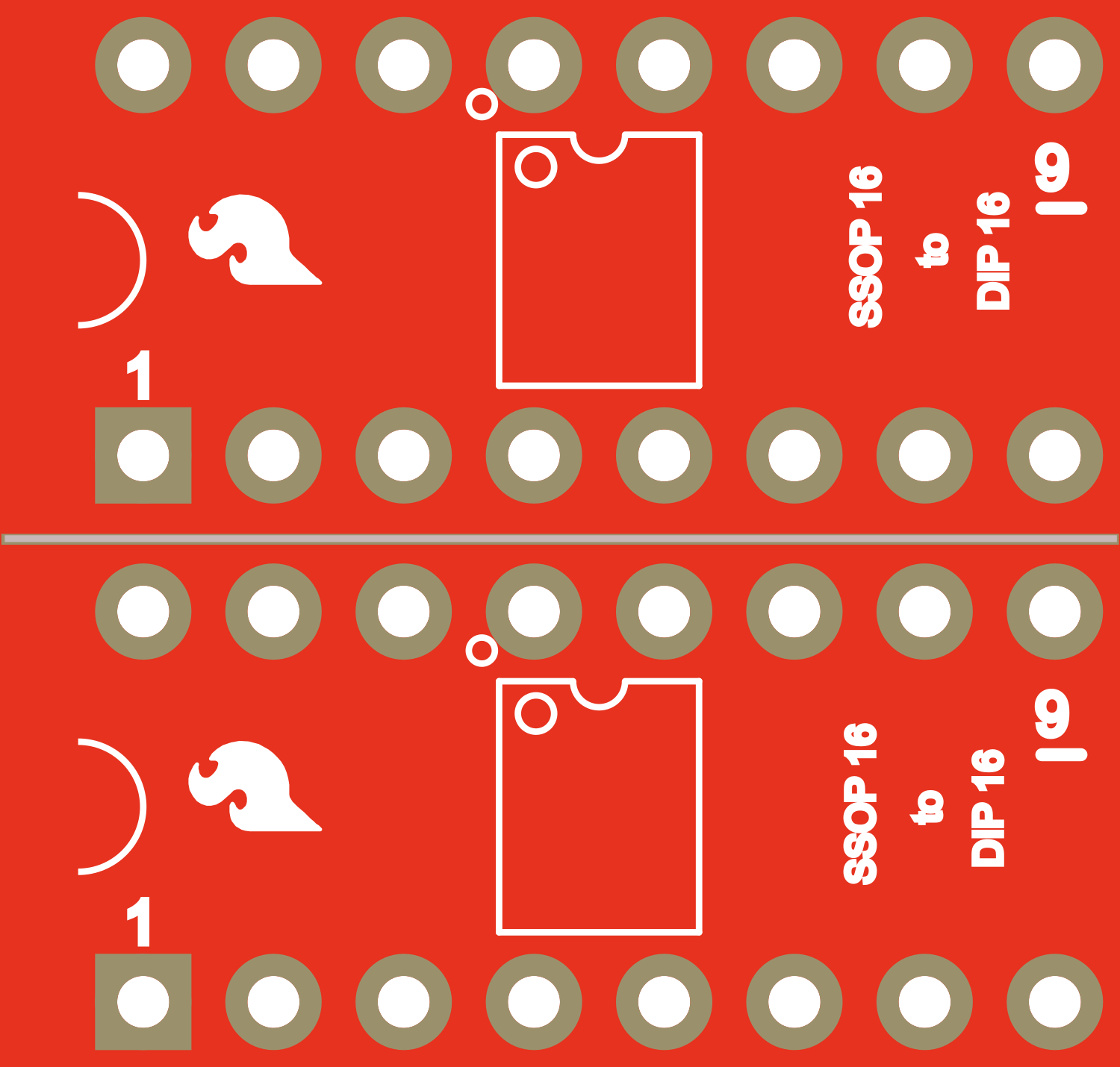
The SparkFun SSOP to DIP Adapter - 16-Pin is a versatile and essential tool for electronics enthusiasts and professionals who need to prototype or test circuits using components in SSOP (Shrink Small Outline Package) form. This adapter board is designed to convert a 16-pin SSOP integrated circuit to a standard 16-pin DIP (Dual In-line Package) footprint, making it compatible with breadboards and through-hole soldering applications. Common use cases include prototyping, testing new ICs, and educational purposes to learn about new or existing SSOP components.

Explore Projects Built with SparkFun SSOP to DIP Adapter - 16-Pin

Use Cirkit Designer to design, explore, and prototype these projects online. Some projects support real-time simulation. Click "Open Project" to start designing instantly!
ESP32-Controlled OLED Display and Servo Circuit
Image of Mailbox: A project utilizing SparkFun SSOP to DIP Adapter - 16-Pin in a practical application
This circuit features an ESP32 microcontroller that is connected to a 0.96" OLED display and a servo motor. The ESP32 uses its I2C interface, with pins D21 and D22 connected to the SDA and SCK pins of the OLED for data display, and pin D18 to control the servo motor via PWM. All components share a common ground and are powered by a 5V adapter, which supplies power to the ESP32's Vin pin, the OLED's VDD pin, and the servo's VCC pin.
Cirkit Designer LogoOpen Project in Cirkit Designer
Battery-Powered ESP32 Data Logger with Oscilloscope Monitoring
Image of electromiografia: A project utilizing SparkFun SSOP to DIP Adapter - 16-Pin in a practical application
This circuit features an ESP32 microcontroller powered by a 7V battery, with its ground connected to a common ground. The ESP32's D35 pin is monitored by a mixed signal oscilloscope, and an alligator clip cable is used to connect the oscilloscope's second channel to the common ground.
Cirkit Designer LogoOpen Project in Cirkit Designer
ESP32 and Logic Level Converter-Based Wi-Fi Controlled Interface
Image of Toshiba AC ESP32 devkit v1: A project utilizing SparkFun SSOP to DIP Adapter - 16-Pin in a practical application
This circuit features an ESP32 Devkit V1 microcontroller connected to a Bi-Directional Logic Level Converter, which facilitates voltage level shifting between the ESP32 and external components. The ESP32 is powered through its VIN pin via an alligator clip cable, and the logic level converter is connected to various pins on the ESP32 to manage different voltage levels for communication.
Cirkit Designer LogoOpen Project in Cirkit Designer
ESP32-Based OLED Display Interface
Image of d: A project utilizing SparkFun SSOP to DIP Adapter - 16-Pin in a practical application
This circuit features an ESP32 microcontroller connected to an OLED 1.3" display. The ESP32's GPIO pins 21 and 22 are used for I2C communication (SDA and SCL respectively) with the OLED display. The display is powered by the 5V output from the ESP32, and both devices share a common ground.
Cirkit Designer LogoOpen Project in Cirkit Designer

Explore Projects Built with SparkFun SSOP to DIP Adapter - 16-Pin

Use Cirkit Designer to design, explore, and prototype these projects online. Some projects support real-time simulation. Click "Open Project" to start designing instantly!
Image of Mailbox: A project utilizing SparkFun SSOP to DIP Adapter - 16-Pin in a practical application
ESP32-Controlled OLED Display and Servo Circuit
This circuit features an ESP32 microcontroller that is connected to a 0.96" OLED display and a servo motor. The ESP32 uses its I2C interface, with pins D21 and D22 connected to the SDA and SCK pins of the OLED for data display, and pin D18 to control the servo motor via PWM. All components share a common ground and are powered by a 5V adapter, which supplies power to the ESP32's Vin pin, the OLED's VDD pin, and the servo's VCC pin.
Cirkit Designer LogoOpen Project in Cirkit Designer
Image of electromiografia: A project utilizing SparkFun SSOP to DIP Adapter - 16-Pin in a practical application
Battery-Powered ESP32 Data Logger with Oscilloscope Monitoring
This circuit features an ESP32 microcontroller powered by a 7V battery, with its ground connected to a common ground. The ESP32's D35 pin is monitored by a mixed signal oscilloscope, and an alligator clip cable is used to connect the oscilloscope's second channel to the common ground.
Cirkit Designer LogoOpen Project in Cirkit Designer
Image of Toshiba AC ESP32 devkit v1: A project utilizing SparkFun SSOP to DIP Adapter - 16-Pin in a practical application
ESP32 and Logic Level Converter-Based Wi-Fi Controlled Interface
This circuit features an ESP32 Devkit V1 microcontroller connected to a Bi-Directional Logic Level Converter, which facilitates voltage level shifting between the ESP32 and external components. The ESP32 is powered through its VIN pin via an alligator clip cable, and the logic level converter is connected to various pins on the ESP32 to manage different voltage levels for communication.
Cirkit Designer LogoOpen Project in Cirkit Designer
Image of d: A project utilizing SparkFun SSOP to DIP Adapter - 16-Pin in a practical application
ESP32-Based OLED Display Interface
This circuit features an ESP32 microcontroller connected to an OLED 1.3" display. The ESP32's GPIO pins 21 and 22 are used for I2C communication (SDA and SCL respectively) with the OLED display. The display is powered by the 5V output from the ESP32, and both devices share a common ground.
Cirkit Designer LogoOpen Project in Cirkit Designer

Technical Specifications

Key Technical Details

  • Compatible Package: 16-pin SSOP
  • Pitch: 0.65mm (distance between pins of SSOP)
  • DIP Pin Spacing: 0.1 inches (2.54mm), standard for breadboards and DIP sockets
  • Board Dimensions: Typically matches the DIP standard sizes
  • Material: FR-4 PCB with HASL finish for soldering ease

Pin Configuration and Descriptions

The following table outlines the pin configuration for the SparkFun SSOP to DIP Adapter - 16-Pin:

SSOP Pin Number DIP Pin Number Description
1 1 Corresponding DIP pin for SSOP pin 1
2 2 Corresponding DIP pin for SSOP pin 2
... ... ...
15 15 Corresponding DIP pin for SSOP pin 15
16 16 Corresponding DIP pin for SSOP pin 16

Usage Instructions

How to Use the Component in a Circuit

  1. Soldering the SSOP IC: Carefully solder the SSOP IC onto the adapter board, ensuring that each pin of the IC aligns with the corresponding pad on the adapter.
  2. Inspection: After soldering, inspect all connections for shorts or cold solder joints.
  3. Insertion into Breadboard/DIP Socket: Once the SSOP IC is securely soldered, insert the adapter into a breadboard or DIP socket as you would with a standard DIP component.

Important Considerations and Best Practices

  • Soldering: Use a fine-tip soldering iron and flux for best results. Soldering SSOP packages requires precision due to the small pitch between pins.
  • Handling: Be cautious when handling the adapter to avoid bending the pins.
  • Static Discharge: Always follow ESD (Electrostatic Discharge) precautions when handling electronic components to prevent damage.

Troubleshooting and FAQs

Common Issues

  • Misalignment: If the IC is not functioning as expected, check for misalignment of pins between the SSOP IC and the adapter.
  • Solder Bridges: Inspect for solder bridges between adjacent pins, which can cause shorts and malfunction.
  • Poor Connectivity: Ensure that the adapter is fully inserted into the breadboard or DIP socket for reliable connectivity.

Solutions and Tips

  • Reflow Solder: If misalignment or solder bridges are detected, reflow the solder with flux and a soldering iron to correct the issue.
  • Pin Straightening: If the DIP pins are bent, carefully straighten them with needle-nose pliers before insertion.
  • Continuity Testing: Use a multimeter to perform continuity tests between the SSOP pins and the corresponding DIP pins to ensure proper connectivity.

FAQs

Q: Can I reuse the adapter for different ICs? A: Yes, but desoldering can be challenging. It's often more practical to use a new adapter for each IC to avoid damage.

Q: Is this adapter compatible with all 16-pin SSOP ICs? A: It is designed for 16-pin SSOP ICs with a 0.65mm pitch. Verify the pitch of your IC before using the adapter.

Q: How can I ensure that the IC is properly aligned before soldering? A: Use a magnifying glass or microscope to check the alignment of the IC pins to the adapter pads before soldering.


Please note that this documentation assumes a basic understanding of electronic components and soldering techniques. If you are new to electronics, consider seeking additional resources or guidance before attempting to use the SparkFun SSOP to DIP Adapter - 16-Pin.