Cirkit Designer Logo
Cirkit Designer
Your all-in-one circuit design IDE
Home / 
Component Documentation

How to Use SCT-013 Current Sensor: Examples, Pinouts, and Specs

Image of SCT-013 Current Sensor
Cirkit Designer LogoDesign with SCT-013 Current Sensor in Cirkit Designer

Introduction

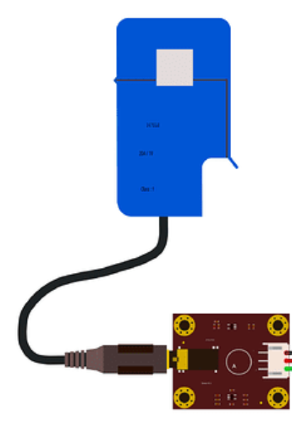
The SCT-013 is a non-invasive current sensor designed to measure alternating current (AC) by clamping around a conductor. Manufactured by Arduino with the part ID Sen0211, this sensor outputs a voltage proportional to the current flowing through the conductor. It is widely used in energy monitoring systems, home automation, and industrial applications to track power consumption and optimize energy usage.

Explore Projects Built with SCT-013 Current Sensor

Use Cirkit Designer to design, explore, and prototype these projects online. Some projects support real-time simulation. Click "Open Project" to start designing instantly!
Wemos S2 Mini Controlled Smart Device with OLED Display, Thermal Printing, and RGB LED Strip
Image of DT NEA - Noah Patel: A project utilizing SCT-013 Current Sensor in a practical application
This circuit features a Wemos S2 Mini microcontroller that controls a WS2812 RGB LED strip and communicates with a 0.96" OLED display and a 58mm mini thermal printer. The ACS712 Current Sensor is interfaced with the microcontroller to monitor current, and power is managed by a CD42 BMS connected to two 18650 Li-ion batteries, with a USB-C PD Trigger Board for power delivery. The circuit is designed for visual output (LED strip, OLED display), printing capabilities, and current sensing, likely for a portable, battery-powered monitoring and display device.
Cirkit Designer LogoOpen Project in Cirkit Designer
STM32 Nucleo F303RE Based Current Monitoring System with LCD Display
Image of Project BMS: A project utilizing SCT-013 Current Sensor in a practical application
This circuit features a current sensor connected to a 7V battery, with the sensor's output connected to an STM32 Nucleo F303RE microcontroller for current monitoring. An NTC thermistor is interfaced with the microcontroller for temperature sensing, and a 16x2 LCD screen is connected via I2C for data display. The circuit includes various resistors for voltage division and current limiting purposes.
Cirkit Designer LogoOpen Project in Cirkit Designer
ESP32-Based Current Monitoring and Temperature Sensing System
Image of SISTEMA DE MONITOREO: A project utilizing SCT-013 Current Sensor in a practical application
This circuit is designed to measure current using an ACS712 Current Sensor and temperature using a DS18B20 sensor, with an ESP32 microcontroller to process and possibly communicate the sensor data. The ACS712 sensor output is connected to one of the ESP32's analog input pins (D34), while the DS18B20's signal line is interfaced with a digital input pin (D23) through a pull-up resistor (4.7k Ohms). The ESP32 is powered through its Vin pin, and both sensors share a common ground with the ESP32.
Cirkit Designer LogoOpen Project in Cirkit Designer
Arduino UNO Based Ammeter with LCD Display
Image of ammeter: A project utilizing SCT-013 Current Sensor in a practical application
This circuit features an Arduino UNO microcontroller interfaced with an ACS712 current sensor and a 16x2 LCD screen using I2C communication. The Arduino reads the current value from the sensor and displays it on the LCD screen, also sending the data to the serial monitor. It is designed to function as an ammeter, measuring and displaying the current flowing through the sensor.
Cirkit Designer LogoOpen Project in Cirkit Designer

Explore Projects Built with SCT-013 Current Sensor

Use Cirkit Designer to design, explore, and prototype these projects online. Some projects support real-time simulation. Click "Open Project" to start designing instantly!
Image of DT NEA - Noah Patel: A project utilizing SCT-013 Current Sensor in a practical application
Wemos S2 Mini Controlled Smart Device with OLED Display, Thermal Printing, and RGB LED Strip
This circuit features a Wemos S2 Mini microcontroller that controls a WS2812 RGB LED strip and communicates with a 0.96" OLED display and a 58mm mini thermal printer. The ACS712 Current Sensor is interfaced with the microcontroller to monitor current, and power is managed by a CD42 BMS connected to two 18650 Li-ion batteries, with a USB-C PD Trigger Board for power delivery. The circuit is designed for visual output (LED strip, OLED display), printing capabilities, and current sensing, likely for a portable, battery-powered monitoring and display device.
Cirkit Designer LogoOpen Project in Cirkit Designer
Image of Project BMS: A project utilizing SCT-013 Current Sensor in a practical application
STM32 Nucleo F303RE Based Current Monitoring System with LCD Display
This circuit features a current sensor connected to a 7V battery, with the sensor's output connected to an STM32 Nucleo F303RE microcontroller for current monitoring. An NTC thermistor is interfaced with the microcontroller for temperature sensing, and a 16x2 LCD screen is connected via I2C for data display. The circuit includes various resistors for voltage division and current limiting purposes.
Cirkit Designer LogoOpen Project in Cirkit Designer
Image of SISTEMA DE MONITOREO: A project utilizing SCT-013 Current Sensor in a practical application
ESP32-Based Current Monitoring and Temperature Sensing System
This circuit is designed to measure current using an ACS712 Current Sensor and temperature using a DS18B20 sensor, with an ESP32 microcontroller to process and possibly communicate the sensor data. The ACS712 sensor output is connected to one of the ESP32's analog input pins (D34), while the DS18B20's signal line is interfaced with a digital input pin (D23) through a pull-up resistor (4.7k Ohms). The ESP32 is powered through its Vin pin, and both sensors share a common ground with the ESP32.
Cirkit Designer LogoOpen Project in Cirkit Designer
Image of ammeter: A project utilizing SCT-013 Current Sensor in a practical application
Arduino UNO Based Ammeter with LCD Display
This circuit features an Arduino UNO microcontroller interfaced with an ACS712 current sensor and a 16x2 LCD screen using I2C communication. The Arduino reads the current value from the sensor and displays it on the LCD screen, also sending the data to the serial monitor. It is designed to function as an ammeter, measuring and displaying the current flowing through the sensor.
Cirkit Designer LogoOpen Project in Cirkit Designer

Common Applications

  • Energy monitoring in residential, commercial, and industrial settings
  • Smart home automation systems
  • Power consumption analysis for appliances
  • Renewable energy systems (e.g., solar or wind power monitoring)
  • Overcurrent detection in electrical systems

Technical Specifications

The SCT-013 current sensor is designed for ease of use and compatibility with microcontrollers like Arduino. Below are its key technical details:

Parameter Value
Manufacturer Arduino
Part ID Sen0211 with SCT-013
Measurement Range 0–100A AC (varies by model)
Output Signal Voltage (proportional to current)
Output Voltage Range 0–1V AC (typical)
Core Material Ferrite
Accuracy ±1% (typical)
Operating Temperature -25°C to +70°C
Cable Length 1 meter
Isolation Voltage 600V AC

Pin Configuration and Descriptions

The SCT-013 sensor has a 3.5mm audio jack for its output. The pinout of the audio jack is as follows:

Pin Description
Tip Signal output (voltage proportional to current)
Ring Not connected (varies by model)
Sleeve Ground

Usage Instructions

The SCT-013 current sensor is straightforward to use in a circuit. Below are the steps and best practices for integrating it into your project:

Connecting the Sensor

  1. Clamp the Sensor: Open the clamp and place it around the live or neutral wire of the AC circuit you want to measure. Ensure the wire is fully enclosed within the clamp for accurate readings.
  2. Connect to a Burden Resistor: The SCT-013 outputs a small AC voltage proportional to the current. To convert this to a measurable voltage for an ADC (Analog-to-Digital Converter), connect a burden resistor across the sensor's output.
  3. Connect to Microcontroller: Use the 3.5mm audio jack to connect the sensor to your circuit. The signal output (tip) should be connected to the ADC input of your microcontroller, and the ground (sleeve) to the microcontroller's ground.
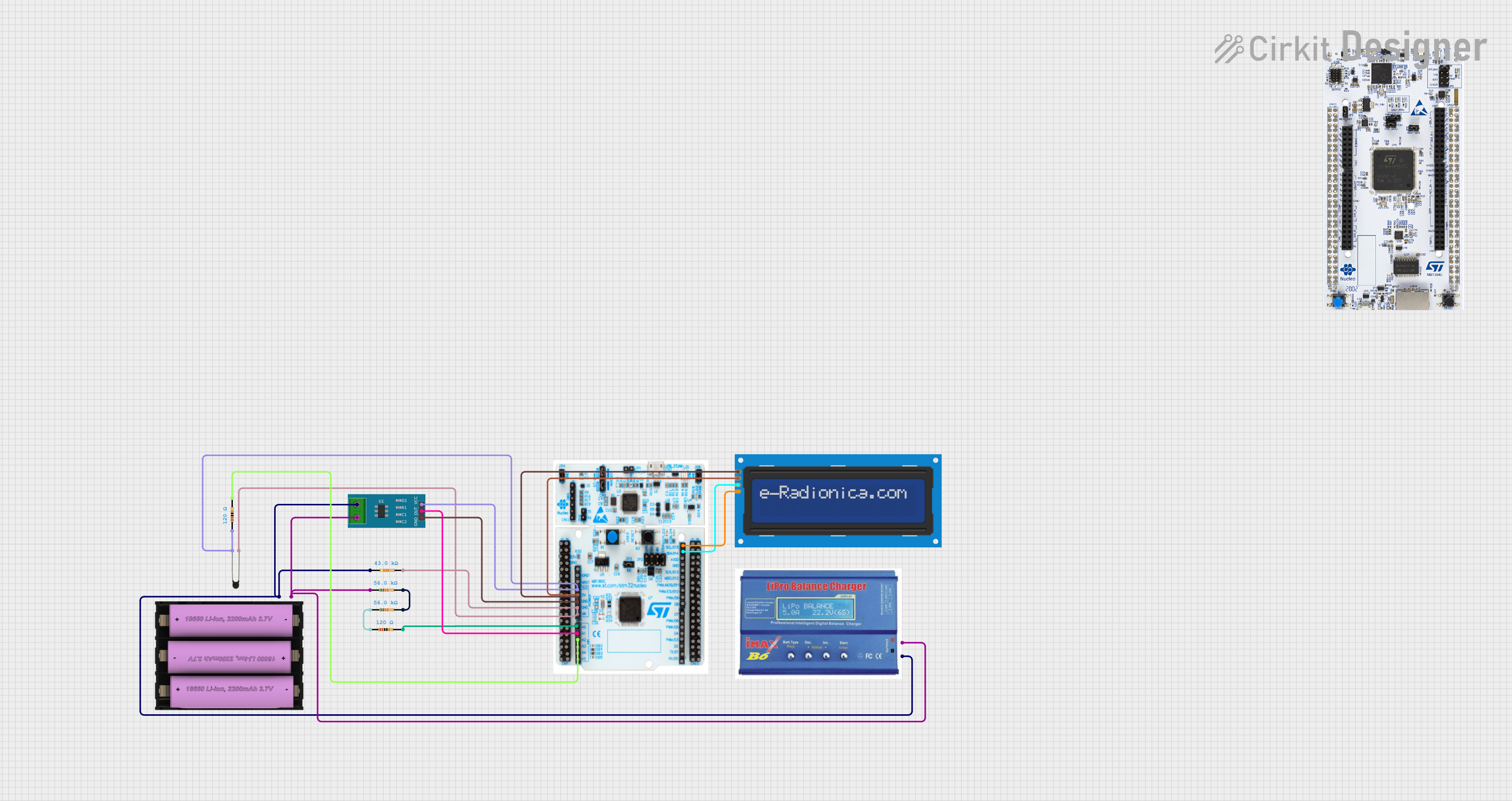
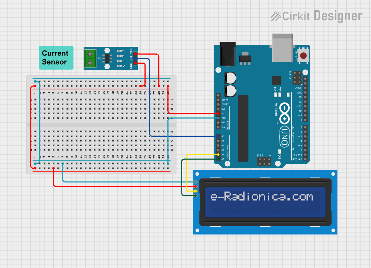
Example Circuit

Below is a simple circuit diagram for connecting the SCT-013 to an Arduino UNO:

SCT-013 Sensor
   |--- Tip (Signal) ----> A0 (Arduino ADC Pin)
   |--- Sleeve (Ground) --> GND (Arduino Ground)

Sample Arduino Code

The following Arduino code demonstrates how to read current values from the SCT-013 sensor:

// Include necessary libraries
const int sensorPin = A0; // Analog pin connected to SCT-013 signal output
const float burdenResistor = 100.0; // Burden resistor value in ohms
const float calibrationFactor = 30.0; // Calibration factor for current calculation

void setup() {
  Serial.begin(9600); // Initialize serial communication
}

void loop() {
  int sensorValue = analogRead(sensorPin); // Read ADC value
  float voltage = (sensorValue / 1023.0) * 5.0; // Convert ADC value to voltage
  float current = (voltage / burdenResistor) * calibrationFactor; 
  // Calculate current using calibration factor

  Serial.print("Current: ");
  Serial.print(current, 2); // Print current value with 2 decimal places
  Serial.println(" A"); // Append unit (Amperes)

  delay(1000); // Wait for 1 second before next reading
}

Important Considerations

  • AC Only: The SCT-013 is designed for AC current measurement and cannot measure DC current.
  • Single Conductor: Ensure the sensor clamps around a single conductor (live or neutral), not the entire cable, as this will result in incorrect readings.
  • Calibration: The calibration factor may vary depending on the specific model of the SCT-013 and the burden resistor used. Perform a calibration test for accurate results.
  • Safety: Always handle the sensor and electrical wiring with care. Ensure the circuit is powered off before clamping the sensor.

Troubleshooting and FAQs

Common Issues and Solutions

  1. No Output Signal

    • Cause: The sensor is not clamped around a conductor or the conductor is carrying no current.
    • Solution: Ensure the sensor is properly clamped around a live or neutral wire with current flowing through it.
  2. Incorrect Readings

    • Cause: The burden resistor value is incorrect or the calibration factor is not set properly.
    • Solution: Verify the burden resistor value and adjust the calibration factor in the code.
  3. Fluctuating Readings

    • Cause: Electrical noise or loose connections.
    • Solution: Use shielded cables and ensure all connections are secure.
  4. Sensor Overheating

    • Cause: The sensor is exposed to high temperatures or excessive current.
    • Solution: Ensure the sensor is operating within its specified temperature and current range.

FAQs

Q: Can the SCT-013 measure DC current?
A: No, the SCT-013 is designed specifically for AC current measurement.

Q: What is the purpose of the burden resistor?
A: The burden resistor converts the small AC current output of the sensor into a measurable AC voltage.

Q: Can I use the SCT-013 with a Raspberry Pi?
A: Yes, but you will need an external ADC module since the Raspberry Pi does not have built-in analog input pins.

Q: How do I calibrate the sensor?
A: Use a known current source and adjust the calibration factor in your code until the readings match the actual current.

By following this documentation, you can effectively integrate the SCT-013 current sensor into your projects for accurate and reliable AC current measurement.