Cirkit Designer Logo
Cirkit Designer
Your all-in-one circuit design IDE
Home / 
Component Documentation

How to Use MAX30102: Examples, Pinouts, and Specs

Image of MAX30102
Cirkit Designer LogoDesign with MAX30102 in Cirkit Designer

Introduction

The MAX30102 is a pulse oximeter and heart-rate sensor module designed for non-invasive health monitoring applications. It utilizes photoplethysmography (PPG) technology to measure blood oxygen saturation (SpO2) and heart rate. The module integrates red and infrared LEDs, a photodetector, optical elements, and low-noise electronics in a compact package, making it ideal for wearable devices, fitness trackers, and medical monitoring systems.

Explore Projects Built with MAX30102

Use Cirkit Designer to design, explore, and prototype these projects online. Some projects support real-time simulation. Click "Open Project" to start designing instantly!
Battery-Powered Health Monitoring System with Nucleo WB55RG and OLED Display
Image of Pulsefex: A project utilizing MAX30102 in a practical application
This circuit is a multi-sensor data acquisition system that uses a Nucleo WB55RG microcontroller to interface with a digital temperature sensor (TMP102), a pulse oximeter and heart-rate sensor (MAX30102), and a 0.96" OLED display via I2C. Additionally, it includes a Sim800l module for GSM communication, powered by a 3.7V LiPo battery.
Cirkit Designer LogoOpen Project in Cirkit Designer
ESP32-Based Multi-Sensor Health Monitoring System with Bluetooth Connectivity
Image of circuit diagram: A project utilizing MAX30102 in a practical application
This circuit features an ESP32-WROOM-32UE microcontroller as the central processing unit, interfacing with a variety of sensors and modules. It includes a MAX30100 pulse oximeter and heart-rate sensor, an MLX90614 infrared thermometer, an HC-05 Bluetooth module for wireless communication, and a Neo 6M GPS module for location tracking. All components are powered by a common voltage supply and are connected to specific GPIO pins on the ESP32 for data exchange, with the sensors using I2C communication and the modules using UART.
Cirkit Designer LogoOpen Project in Cirkit Designer
ESP32 and MAX30100 Pulse Oximeter
Image of t: A project utilizing MAX30102 in a practical application
This circuit features an ESP32 microcontroller connected to a MAX30100 sensor, which is likely used for measuring pulse oximetry. The ESP32 is interfaced with the MAX30100 via I2C communication, as indicated by the SDA and SCL connections. Power is supplied to both the ESP32 and the MAX30100 by a 5V battery, with common ground established across the components.
Cirkit Designer LogoOpen Project in Cirkit Designer
ESP32-Based Health Monitoring System with Bluetooth and GPS
Image of circuit diagram: A project utilizing MAX30102 in a practical application
This circuit integrates an ESP32 microcontroller with various sensors and modules, including a MAX30100 pulse oximeter, an MLX90614 infrared thermometer, a Neo 6M GPS module, and an HC-05 Bluetooth module. The ESP32 collects data from these sensors and modules via I2C and UART interfaces, enabling wireless communication and GPS tracking capabilities.
Cirkit Designer LogoOpen Project in Cirkit Designer

Explore Projects Built with MAX30102

Use Cirkit Designer to design, explore, and prototype these projects online. Some projects support real-time simulation. Click "Open Project" to start designing instantly!
Image of Pulsefex: A project utilizing MAX30102 in a practical application
Battery-Powered Health Monitoring System with Nucleo WB55RG and OLED Display
This circuit is a multi-sensor data acquisition system that uses a Nucleo WB55RG microcontroller to interface with a digital temperature sensor (TMP102), a pulse oximeter and heart-rate sensor (MAX30102), and a 0.96" OLED display via I2C. Additionally, it includes a Sim800l module for GSM communication, powered by a 3.7V LiPo battery.
Cirkit Designer LogoOpen Project in Cirkit Designer
Image of circuit diagram: A project utilizing MAX30102 in a practical application
ESP32-Based Multi-Sensor Health Monitoring System with Bluetooth Connectivity
This circuit features an ESP32-WROOM-32UE microcontroller as the central processing unit, interfacing with a variety of sensors and modules. It includes a MAX30100 pulse oximeter and heart-rate sensor, an MLX90614 infrared thermometer, an HC-05 Bluetooth module for wireless communication, and a Neo 6M GPS module for location tracking. All components are powered by a common voltage supply and are connected to specific GPIO pins on the ESP32 for data exchange, with the sensors using I2C communication and the modules using UART.
Cirkit Designer LogoOpen Project in Cirkit Designer
Image of t: A project utilizing MAX30102 in a practical application
ESP32 and MAX30100 Pulse Oximeter
This circuit features an ESP32 microcontroller connected to a MAX30100 sensor, which is likely used for measuring pulse oximetry. The ESP32 is interfaced with the MAX30100 via I2C communication, as indicated by the SDA and SCL connections. Power is supplied to both the ESP32 and the MAX30100 by a 5V battery, with common ground established across the components.
Cirkit Designer LogoOpen Project in Cirkit Designer
Image of circuit diagram: A project utilizing MAX30102 in a practical application
ESP32-Based Health Monitoring System with Bluetooth and GPS
This circuit integrates an ESP32 microcontroller with various sensors and modules, including a MAX30100 pulse oximeter, an MLX90614 infrared thermometer, a Neo 6M GPS module, and an HC-05 Bluetooth module. The ESP32 collects data from these sensors and modules via I2C and UART interfaces, enabling wireless communication and GPS tracking capabilities.
Cirkit Designer LogoOpen Project in Cirkit Designer

Common Applications

  • Wearable health monitoring devices
  • Fitness trackers
  • Medical-grade pulse oximeters
  • Heart rate monitoring systems
  • IoT-based health monitoring solutions

Technical Specifications

Key Technical Details

Parameter Value
Supply Voltage 1.8V (core) and 3.3V (LED driver)
Operating Current 600 µA (typical)
Standby Current 0.7 µA
Measurement Method Photoplethysmography (PPG)
LED Wavelengths Red: 660 nm, Infrared: 880 nm
Communication Interface I2C
Operating Temperature Range -40°C to +85°C
Dimensions 5.6 mm x 3.3 mm x 1.55 mm

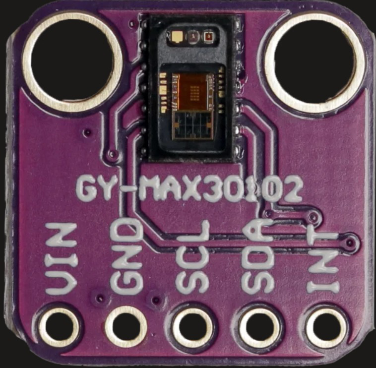
Pin Configuration and Descriptions

The MAX30102 module typically comes with the following pinout:

Pin Name Pin Number Description
VIN 1 Power supply input (3.3V recommended)
GND 2 Ground
SDA 3 I2C data line
SCL 4 I2C clock line
INT 5 Interrupt output (active low)

Usage Instructions

How to Use the MAX30102 in a Circuit

  1. Power Supply: Connect the VIN pin to a 3.3V power source and the GND pin to ground.
  2. I2C Communication: Connect the SDA and SCL pins to the corresponding I2C pins on your microcontroller (e.g., Arduino UNO).
  3. Interrupt Pin: Optionally, connect the INT pin to a GPIO pin on your microcontroller to handle interrupts.
  4. Pull-Up Resistors: Use 4.7kΩ pull-up resistors on the SDA and SCL lines if not already present on the module.
  5. Placement: Ensure the sensor is placed close to the skin for accurate readings, with minimal ambient light interference.

Important Considerations

  • Avoid exposing the sensor to direct sunlight or strong ambient light, as this can affect accuracy.
  • Ensure proper alignment of the sensor with the skin for consistent readings.
  • Use a low-noise power supply to minimize interference.

Example Code for Arduino UNO

Below is an example of how to interface the MAX30102 with an Arduino UNO using the Adafruit MAX30102 library:

#include <Wire.h>
#include "Adafruit_MAX30102.h"

// Create an instance of the MAX30102 sensor
Adafruit_MAX30102 max30102;

void setup() {
  Serial.begin(9600); // Initialize serial communication
  while (!Serial);    // Wait for the serial monitor to open

  // Initialize the I2C communication
  if (!max30102.begin()) {
    Serial.println("MAX30102 not detected. Check connections.");
    while (1); // Halt execution if the sensor is not found
  }

  Serial.println("MAX30102 initialized successfully.");
}

void loop() {
  // Variables to store sensor readings
  int redValue, irValue;

  // Read data from the sensor
  if (max30102.check() == true) {
    redValue = max30102.getRed(); // Get red LED value
    irValue = max30102.getIR();  // Get infrared LED value

    // Print the readings to the serial monitor
    Serial.print("Red: ");
    Serial.print(redValue);
    Serial.print(" | IR: ");
    Serial.println(irValue);
  } else {
    Serial.println("No data available.");
  }

  delay(100); // Delay for stability
}

Notes on the Code

  • Install the Adafruit MAX30102 library via the Arduino Library Manager before running the code.
  • Ensure the I2C address of the MAX30102 matches the library's default (0x57). If not, modify the library or use a different address.

Troubleshooting and FAQs

Common Issues and Solutions

  1. Sensor Not Detected:

    • Ensure proper wiring of the SDA and SCL pins.
    • Verify that pull-up resistors are present on the I2C lines.
    • Check the power supply voltage (3.3V recommended).
  2. Inaccurate Readings:

    • Ensure the sensor is in contact with the skin and properly aligned.
    • Avoid strong ambient light or reflective surfaces near the sensor.
    • Use a low-noise power source to reduce interference.
  3. No Data Available:

    • Verify that the sensor is initialized correctly in the code.
    • Check the interrupt pin connection if using interrupts.

FAQs

Q: Can the MAX30102 be powered with 5V?
A: No, the MAX30102 requires a 3.3V power supply. Using 5V can damage the module.

Q: What is the maximum I2C clock speed supported?
A: The MAX30102 supports I2C clock speeds up to 400 kHz.

Q: Can the MAX30102 measure SpO2 and heart rate simultaneously?
A: Yes, the MAX30102 can measure both parameters simultaneously using its red and infrared LEDs.

Q: How do I improve measurement accuracy?
A: Ensure proper sensor placement, minimize ambient light interference, and use a stable power supply.

This concludes the documentation for the MAX30102. For further assistance, refer to the official datasheet or community forums.