How to Use CPU Fan: Examples, Pinouts, and Specs
Introduction
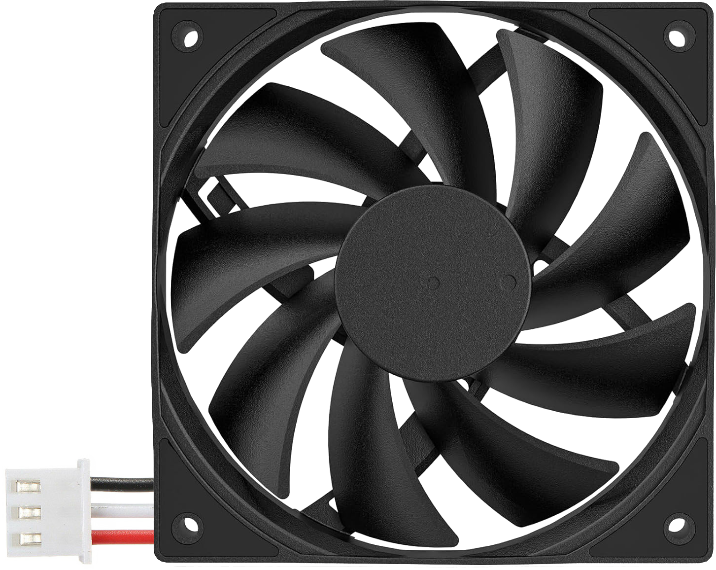
A CPU fan, such as the DARKROCK B0CD7P3S8Q, is a critical cooling device designed to dissipate heat generated by the central processing unit (CPU) of a computer. By maintaining optimal operating temperatures, the CPU fan ensures the reliable performance and longevity of the processor. It is typically mounted on top of a heatsink, which further aids in heat dissipation.
Explore Projects Built with CPU Fan

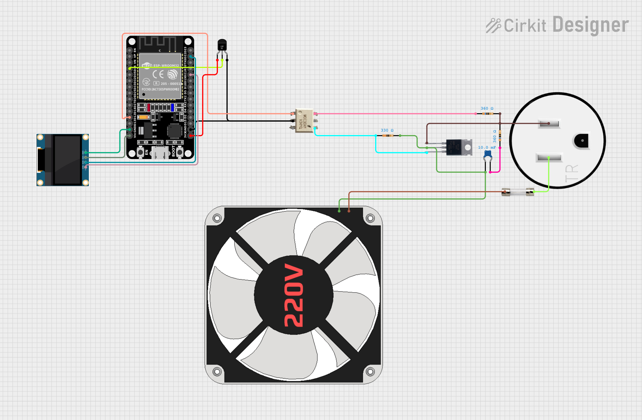
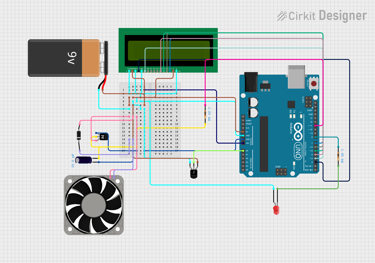

Explore Projects Built with CPU Fan
Common Applications and Use Cases
- Cooling CPUs in desktop computers, gaming rigs, and workstations.
- Preventing thermal throttling during high-performance tasks such as gaming, video rendering, or data processing.
- Maintaining system stability and extending the lifespan of the CPU.
Technical Specifications
Key Technical Details
| Parameter | Specification |
|---|---|
| Manufacturer | DARKROCK |
| Part ID | B0CD7P3S8Q |
| Fan Dimensions | 120mm x 120mm x 25mm |
| Rated Voltage | 12V DC |
| Operating Voltage Range | 7V - 13.2V |
| Current Consumption | 0.2A |
| Power Consumption | 2.4W |
| Fan Speed | 600 - 1500 RPM (±10%) |
| Airflow | 50 CFM (Cubic Feet per Minute) |
| Noise Level | 20 dBA (at maximum speed) |
| Connector Type | 4-pin PWM (Pulse Width Modulation) |
| Bearing Type | Fluid Dynamic Bearing (FDB) |
| Lifespan | 50,000 hours |
Pin Configuration and Descriptions
| Pin Number | Pin Name | Description |
|---|---|---|
| 1 | GND | Ground connection for the fan. |
| 2 | +12V | Power supply for the fan (12V DC). |
| 3 | Tachometer | Outputs a signal to monitor the fan's speed (RPM). |
| 4 | PWM | Pulse Width Modulation input for controlling the fan speed dynamically. |
Usage Instructions
How to Use the Component in a Circuit
- Mounting the Fan: Secure the DARKROCK B0CD7P3S8Q CPU fan onto the CPU heatsink using the provided screws or mounting clips. Ensure proper alignment for optimal airflow.
- Connecting the Fan:
- Plug the 4-pin connector into the CPU_FAN header on the motherboard.
- Ensure the connector is properly seated to avoid loose connections.
- Configuring Fan Speed:
- Use the BIOS/UEFI settings to enable PWM control for the CPU fan.
- Adjust fan speed profiles (e.g., silent, balanced, or performance) based on your cooling needs.
Important Considerations and Best Practices
- Airflow Direction: Ensure the fan is oriented correctly to push air through the heatsink and out of the case.
- Cable Management: Route the fan cable neatly to avoid interference with other components or airflow.
- Thermal Paste: Apply a thin, even layer of thermal paste between the CPU and heatsink for efficient heat transfer.
- Dust Management: Periodically clean the fan and heatsink to prevent dust buildup, which can reduce cooling efficiency.
Example: Controlling the Fan with an Arduino UNO
The DARKROCK B0CD7P3S8Q fan can be controlled using an Arduino UNO via PWM. Below is an example code to adjust the fan speed:
// Define the PWM pin connected to the fan's PWM input
const int fanPWMPin = 9;

void setup() {
  // Set the PWM pin as an output
  pinMode(fanPWMPin, OUTPUT);
}

void loop() {
  // Example: Gradually increase and decrease fan speed
  for (int speed = 0; speed <= 255; speed++) {
    analogWrite(fanPWMPin, speed); // Set fan speed (0-255)
    delay(20); // Wait 20ms before increasing speed
  }
  for (int speed = 255; speed >= 0; speed--) {
    analogWrite(fanPWMPin, speed); // Decrease fan speed
    delay(20); // Wait 20ms before decreasing speed
  }
}
Notes:
- The
analogWrite()function generates a PWM signal to control the fan speed. - Ensure the Arduino's ground (GND) is connected to the fan's ground (GND) for proper operation.
Troubleshooting and FAQs
Common Issues and Solutions
Fan Not Spinning:
- Cause: Loose or incorrect connection.
- Solution: Check the 4-pin connector and ensure it is securely plugged into the CPU_FAN header.
Excessive Noise:
- Cause: Dust buildup or fan running at maximum speed.
- Solution: Clean the fan and heatsink. Adjust the fan speed profile in the BIOS/UEFI.
Overheating CPU:
- Cause: Improper mounting or insufficient thermal paste.
- Solution: Reapply thermal paste and ensure the fan and heatsink are securely mounted.
Fan Speed Not Changing:
- Cause: PWM control not enabled.
- Solution: Enable PWM control in the BIOS/UEFI or verify the PWM signal from the controller.
FAQs
Q: Can I use this fan with a 3-pin header?
A: Yes, but PWM speed control will not function. The fan will run at a constant speed.Q: How often should I clean the fan?
A: Clean the fan and heatsink every 3-6 months, or more frequently in dusty environments.Q: What happens if the fan fails?
A: The CPU may overheat, leading to thermal throttling or shutdown. Replace the fan immediately if it fails.Q: Can I use this fan for overclocking?
A: Yes, but ensure your case has adequate airflow and consider additional cooling solutions if needed.