Cirkit Designer Logo
Cirkit Designer
Your all-in-one circuit design IDE
Home / 
Component Documentation

How to Use rf module tx: Examples, Pinouts, and Specs

Image of rf module tx
Cirkit Designer LogoDesign with rf module tx in Cirkit Designer

Introduction

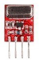
The RF Module TX (A88) is a compact radio frequency transmitter module designed for wireless communication applications. It operates by sending signals at a specific frequency and is commonly used in remote control systems, telemetry, wireless alarm systems, and various DIY projects. The module's ease of use and low cost make it a popular choice for hobbyists and professionals alike.

Explore Projects Built with rf module tx

Use Cirkit Designer to design, explore, and prototype these projects online. Some projects support real-time simulation. Click "Open Project" to start designing instantly!
Arduino UNO with 433MHz RF Module for Wireless Communication
Image of Receiver: A project utilizing rf module tx in a practical application
This circuit consists of an Arduino UNO connected to an RXN433MHz radio frequency module. The Arduino provides 5V power and ground to the RF module and is configured to communicate with it via digital pin D11. Additionally, a multimeter is connected with alligator clip cables to measure the voltage supplied to the RF module.
Cirkit Designer LogoOpen Project in Cirkit Designer
Dual-Mode LoRa and GSM Communication Device with ESP32
Image of modul gateway: A project utilizing rf module tx in a practical application
This circuit features an ESP32 Devkit V1 microcontroller interfaced with an RFM95 LoRa transceiver module for long-range communication and a SIM800L GSM module for cellular connectivity. Two LM2596 step-down modules are used to regulate the 12V battery voltage down to 3.3V required by the ESP32, RFM95, and SIM800L. The ESP32 facilitates data exchange between the RFM95 and SIM800L, enabling the system to send/receive data over both LoRa and GSM networks.
Cirkit Designer LogoOpen Project in Cirkit Designer
ESP32-Based RF Communication System with 433 MHz Modules
Image of 433 mhz: A project utilizing rf module tx in a practical application
This circuit comprises an ESP32 microcontroller connected to a 433 MHz RF transmitter and receiver pair. The ESP32 is programmed to receive and decode RF signals through the receiver module, as well as send RF signals via the transmitter module. Additionally, the ESP32 can communicate with a Bluetooth device to exchange commands and data, and it uses an LED for status indication.
Cirkit Designer LogoOpen Project in Cirkit Designer
433 MHz RF Transmitter and Receiver with Arduino Uno for Wireless LED Control
Image of rf module up: A project utilizing rf module tx in a practical application
This circuit consists of two Arduino Uno R3 microcontrollers communicating wirelessly using 433 MHz RF modules. One Arduino is connected to an RF transmitter to send data, while the other Arduino is connected to an RF receiver to receive data and control an LED based on the received signal.
Cirkit Designer LogoOpen Project in Cirkit Designer

Explore Projects Built with rf module tx

Use Cirkit Designer to design, explore, and prototype these projects online. Some projects support real-time simulation. Click "Open Project" to start designing instantly!
Image of Receiver: A project utilizing rf module tx in a practical application
Arduino UNO with 433MHz RF Module for Wireless Communication
This circuit consists of an Arduino UNO connected to an RXN433MHz radio frequency module. The Arduino provides 5V power and ground to the RF module and is configured to communicate with it via digital pin D11. Additionally, a multimeter is connected with alligator clip cables to measure the voltage supplied to the RF module.
Cirkit Designer LogoOpen Project in Cirkit Designer
Image of modul gateway: A project utilizing rf module tx in a practical application
Dual-Mode LoRa and GSM Communication Device with ESP32
This circuit features an ESP32 Devkit V1 microcontroller interfaced with an RFM95 LoRa transceiver module for long-range communication and a SIM800L GSM module for cellular connectivity. Two LM2596 step-down modules are used to regulate the 12V battery voltage down to 3.3V required by the ESP32, RFM95, and SIM800L. The ESP32 facilitates data exchange between the RFM95 and SIM800L, enabling the system to send/receive data over both LoRa and GSM networks.
Cirkit Designer LogoOpen Project in Cirkit Designer
Image of 433 mhz: A project utilizing rf module tx in a practical application
ESP32-Based RF Communication System with 433 MHz Modules
This circuit comprises an ESP32 microcontroller connected to a 433 MHz RF transmitter and receiver pair. The ESP32 is programmed to receive and decode RF signals through the receiver module, as well as send RF signals via the transmitter module. Additionally, the ESP32 can communicate with a Bluetooth device to exchange commands and data, and it uses an LED for status indication.
Cirkit Designer LogoOpen Project in Cirkit Designer
Image of rf module up: A project utilizing rf module tx in a practical application
433 MHz RF Transmitter and Receiver with Arduino Uno for Wireless LED Control
This circuit consists of two Arduino Uno R3 microcontrollers communicating wirelessly using 433 MHz RF modules. One Arduino is connected to an RF transmitter to send data, while the other Arduino is connected to an RF receiver to receive data and control an LED based on the received signal.
Cirkit Designer LogoOpen Project in Cirkit Designer

Common Applications and Use Cases

  • Remote control for consumer electronics
  • Wireless data transmission for sensors
  • Home automation systems
  • DIY wireless communication projects
  • Telemetry systems for data logging

Technical Specifications

Key Technical Details

  • Operating Frequency: Typically 433 MHz or 315 MHz
  • Modulation Technique: Amplitude Shift Keying (ASK)
  • Supply Voltage: 3V to 12V DC
  • Operating Current: 10mA (typical at 5V)
  • Output Power: 4-16 dBm (depending on supply voltage)
  • Communication Range: 20-200 meters (without obstacles, antenna dependent)
  • Operating Temperature: -20°C to +70°C

Pin Configuration and Descriptions

Pin Number Pin Name Description
1 VCC Power supply (3V to 12V DC)
2 GND Ground
3 DATA Data input for modulation
4 ANT Antenna connection (typically a 17cm wire)

Usage Instructions

How to Use the Component in a Circuit

  1. Power Supply: Connect the VCC pin to a DC power supply within the specified range (3V to 12V) and the GND pin to the ground of the power source.
  2. Data Input: The DATA pin is where the digital signal to be transmitted is applied. This signal should be encoded appropriately for the receiver to decode.
  3. Antenna: Attach an appropriate length antenna to the ANT pin for optimal transmission range. For a 433 MHz module, a 17cm wire antenna is commonly used.
  4. Pairing with Receiver: Ensure that the receiver module is compatible and tuned to the same frequency as the transmitter for successful communication.

Important Considerations and Best Practices

  • Antenna Length: The length of the antenna should be close to the quarter wavelength of the operating frequency for optimal performance.
  • Power Supply: Ensure a stable power supply to avoid transmission errors.
  • Interference: Keep the module away from metal objects and electronic noise sources to minimize interference.
  • Data Rate: The data rate should not exceed the module's bandwidth capabilities.

Troubleshooting and FAQs

Common Issues

  • No Signal Transmission: Check power supply, antenna connection, and ensure the DATA pin is receiving the correct signal.
  • Limited Range: Verify antenna length, avoid obstacles, and increase the power supply voltage if within safe limits.
  • Interference: Change the operating frequency or location to avoid interference with other RF devices.

Solutions and Tips for Troubleshooting

  • Check Connections: Ensure all connections are secure and correct.
  • Power Supply: Verify that the power supply is within the specified range and stable.
  • Antenna: Confirm that the antenna is properly connected and of the correct length.

FAQs

Q: Can I use this module for Wi-Fi or Bluetooth applications? A: No, this module is designed for basic RF communication and is not compatible with Wi-Fi or Bluetooth protocols.

Q: What is the maximum data rate for this module? A: The data rate depends on the specific module and conditions but is typically in the range of 1-10 kbps.

Q: How can I increase the range of the RF module? A: Use a higher voltage within the specified range, ensure the antenna is optimized, and reduce obstacles between the transmitter and receiver.

Example Code for Arduino UNO

// Example code for transmitting data using the RF Module TX (A88) with an Arduino UNO
#include <VirtualWire.h>

const int tx_pin = 12; // TX Module data pin connected to Arduino pin 12

void setup() {
  // Initialize the IO and ISR
  vw_set_tx_pin(tx_pin); // Set the TX pin
  vw_setup(2000);        // Bits per sec
}

void loop() {
  const char *msg = "hello"; // Message to be transmitted

  vw_send((uint8_t *)msg, strlen(msg)); // Send the message
  vw_wait_tx(); // Wait until the whole message is gone
  delay(1000); // Wait for a second before sending the next message
}

Note: This example uses the VirtualWire library, which is commonly used for RF communication with Arduino. Ensure the library is installed in your Arduino IDE before compiling and uploading the code to the Arduino UNO.

Remember to keep code comments concise and within the 80 character line length limit.