How to Use NRF24l01+PA+LNA: Examples, Pinouts, and Specs
Introduction
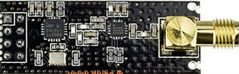
The NRF24L01+PA+LNA is a low-power 2.4 GHz transceiver module designed for wireless communication. It features a built-in Power Amplifier (PA) and Low Noise Amplifier (LNA), which significantly enhance its range and sensitivity compared to the standard NRF24L01 module. This makes it ideal for applications requiring long-range and reliable communication.
Explore Projects Built with NRF24l01+PA+LNA
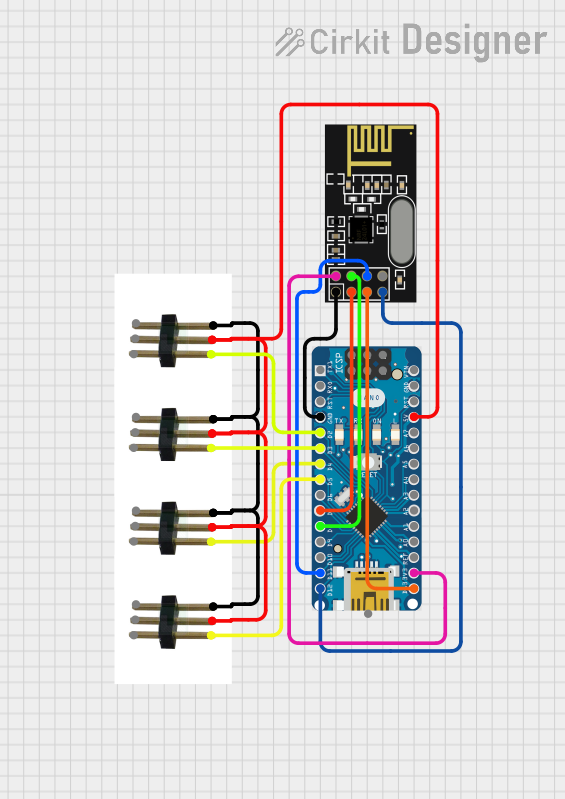
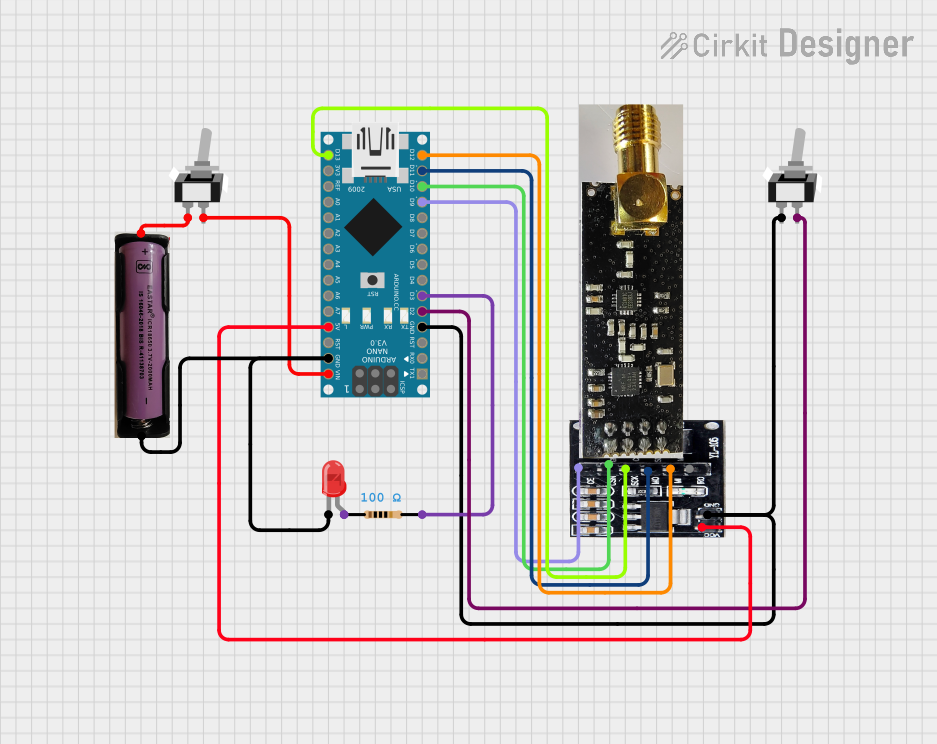

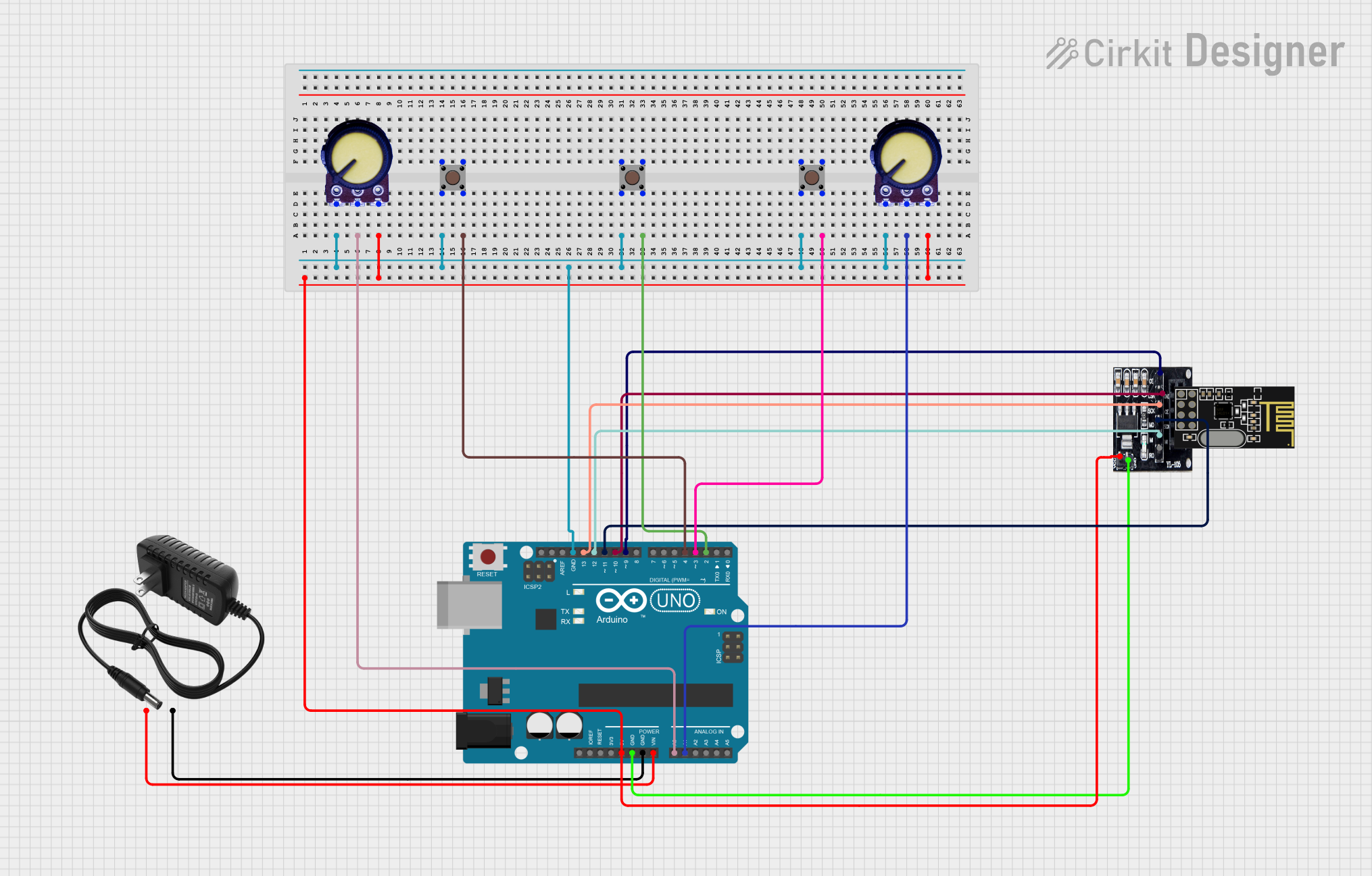
Explore Projects Built with NRF24l01+PA+LNA
Common Applications and Use Cases
- Wireless sensor networks
- Remote control systems (e.g., drones, RC cars)
- Home automation
- Industrial monitoring and control
- Internet of Things (IoT) devices
- Wireless data transmission between microcontrollers
Technical Specifications
Key Technical Details
- Frequency Range: 2.4 GHz ISM band
- Operating Voltage: 3.3V (not 5V tolerant)
- Current Consumption:
- Transmit Mode: ~115 mA (at maximum power)
- Receive Mode: ~13.5 mA
- Standby Mode: ~22 µA
- Data Rate: 250 kbps, 1 Mbps, or 2 Mbps
- Output Power: Up to +20 dBm (adjustable)
- Sensitivity: -94 dBm at 1 Mbps
- Communication Protocol: SPI (Serial Peripheral Interface)
- Antenna: External SMA antenna for extended range
- Range: Up to 1,000 meters (line of sight, depending on environment)
Pin Configuration and Descriptions
The NRF24L01+PA+LNA module typically has an 8-pin interface. Below is the pinout and description:
| Pin | Name | Description |
|---|---|---|
| 1 | GND | Ground connection |
| 2 | VCC | Power supply (3.3V only) |
| 3 | CE | Chip Enable: Activates the module for transmitting or receiving data |
| 4 | CSN | Chip Select Not: SPI chip select (active low) |
| 5 | SCK | Serial Clock: SPI clock input |
| 6 | MOSI | Master Out Slave In: SPI data input |
| 7 | MISO | Master In Slave Out: SPI data output |
| 8 | IRQ | Interrupt Request: Indicates data received or transmission complete (optional) |
Usage Instructions
How to Use the NRF24L01+PA+LNA in a Circuit
- Power Supply: Ensure the module is powered with a stable 3.3V source. Do not connect it directly to a 5V supply, as it is not 5V tolerant. Use a voltage regulator if necessary.
- SPI Connection: Connect the module to a microcontroller (e.g., Arduino UNO) via the SPI interface:
- CE, CSN, SCK, MOSI, and MISO pins should be connected to the corresponding SPI pins on the microcontroller.
- Antenna: Attach the external SMA antenna to the module for optimal range and performance.
- Software Configuration: Use an appropriate library (e.g., RF24 library for Arduino) to configure and control the module.
Important Considerations and Best Practices
- Decoupling Capacitor: Place a 10 µF capacitor between VCC and GND to stabilize the power supply.
- Signal Integrity: Use short and direct wires for SPI connections to minimize noise and signal degradation.
- Antenna Placement: Position the antenna away from metal objects and other sources of interference for maximum range.
- Power Supply: If using an Arduino UNO, consider using a separate 3.3V regulator module to power the NRF24L01+PA+LNA, as the Arduino's onboard 3.3V regulator may not provide sufficient current.
Example Code for Arduino UNO
Below is an example of how to use the NRF24L01+PA+LNA module with an Arduino UNO to send and receive data:
#include <SPI.h>
#include <nRF24L01.h>
#include <RF24.h>

// Define CE and CSN pins for the NRF24L01+ module
#define CE_PIN 9
#define CSN_PIN 10

// Create an RF24 object
RF24 radio(CE_PIN, CSN_PIN);

// Define the address for communication
const byte address[6] = "00001";

void setup() {
  Serial.begin(9600); // Initialize serial communication
  radio.begin();      // Initialize the NRF24L01+ module
  radio.openWritingPipe(address); // Set the address for transmitting data
  radio.setPALevel(RF24_PA_HIGH); // Set power amplifier level to high
  radio.stopListening();          // Set the module to transmit mode
}

void loop() {
  const char text[] = "Hello, world!"; // Data to send
  bool success = radio.write(&text, sizeof(text)); // Send data

  if (success) {
    Serial.println("Data sent successfully!");
  } else {
    Serial.println("Data transmission failed.");
  }

  delay(1000); // Wait 1 second before sending again
}
Notes:
- Install the RF24 library in the Arduino IDE before using the code.
- Modify the CE and CSN pin definitions if using different pins on the Arduino.
Troubleshooting and FAQs
Common Issues and Solutions
Module Not Responding:
- Ensure the module is powered with a stable 3.3V supply.
- Verify SPI connections and ensure they match the microcontroller's pinout.
- Check that the CE and CSN pins are correctly defined in the code.
Short Range or Unstable Communication:
- Ensure the external antenna is securely connected.
- Avoid placing the module near sources of interference (e.g., Wi-Fi routers, metal objects).
- Use a decoupling capacitor (10 µF) between VCC and GND.
Data Transmission Fails:
- Verify that the transmitter and receiver are using the same address and data rate.
- Check that the power amplifier level is set appropriately (e.g.,
RF24_PA_HIGH).
Arduino UNO Power Issues:
- The Arduino's onboard 3.3V regulator may not provide enough current for the module. Use an external 3.3V regulator if needed.
FAQs
Can I use the NRF24L01+PA+LNA with a 5V microcontroller?
- Yes, but you must use a logic level shifter or voltage divider for the SPI pins, as the module operates at 3.3V.
What is the maximum range of the module?
- The module can achieve up to 1,000 meters in line-of-sight conditions with the external antenna.
Why is the module not working with my Arduino?
- Double-check the wiring, ensure the module is powered with 3.3V, and verify that the RF24 library is installed and configured correctly.
By following this documentation, you can effectively integrate the NRF24L01+PA+LNA module into your wireless communication projects.