
How to Use Resonator: Examples, Pinouts, and Specs

 Design with Resonator in Cirkit Designer
Introduction
A resonator is a device that oscillates at a specific frequency, making it an essential component in electronic circuits for stabilizing and filtering signals. Resonators are commonly used in oscillators, frequency-selective circuits, and timing applications. They are compact, cost-effective, and reliable, making them a popular choice in consumer electronics, communication devices, and microcontroller-based systems.
Explore Projects Built with Resonator
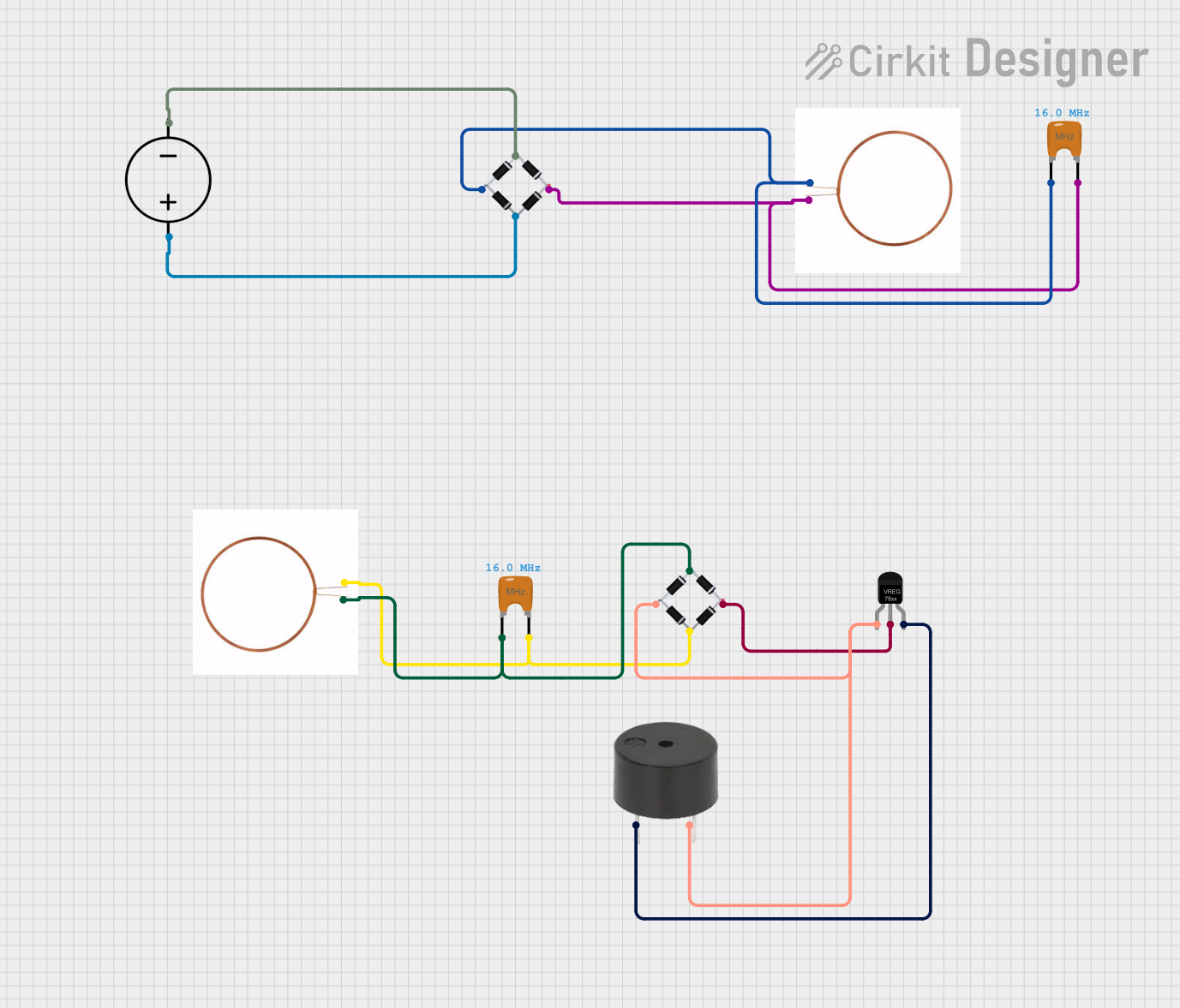 Open Project in Cirkit Designer
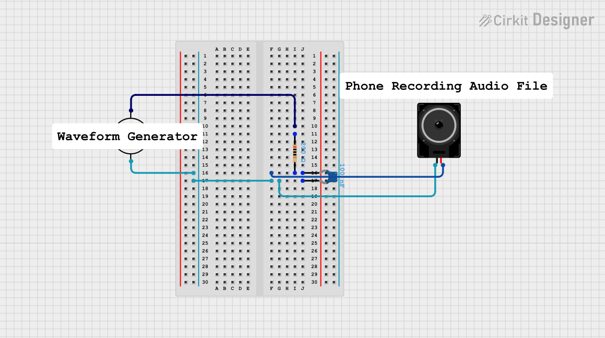 Open Project in Cirkit Designer
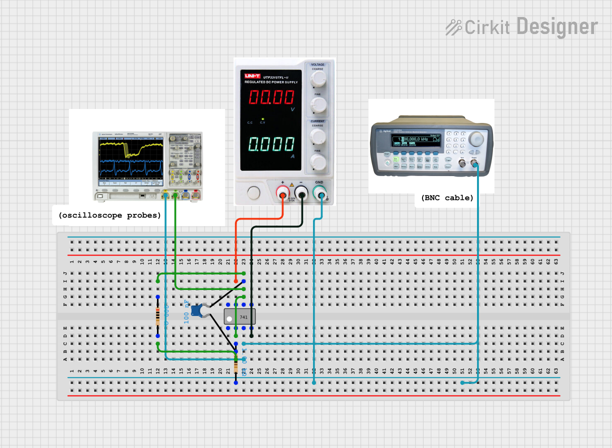 Open Project in Cirkit Designer
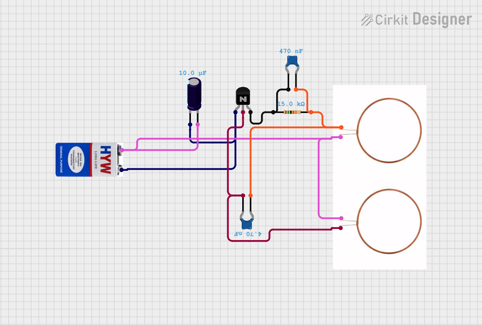 Open Project in Cirkit Designer
Explore Projects Built with Resonator
Open Project in Cirkit DesignerOpen Project in Cirkit DesignerOpen Project in Cirkit DesignerOpen Project in Cirkit DesignerCommon Applications and Use Cases
- Oscillators: Used to generate stable clock signals in microcontrollers and processors.
- Frequency Filters: Employed in RF circuits to select or reject specific frequencies.
- Timing Circuits: Found in devices like watches, timers, and communication systems.
- Wireless Communication: Used in transmitters and receivers for frequency stabilization.
Technical Specifications
Key Technical Details
- Frequency Range: Typically 1 MHz to 50 MHz (varies by model).
- Tolerance: ±0.5% to ±0.1% (depending on the resonator type).
- Operating Voltage: 3.3V to 5V (common for most resonators).
- Temperature Range: -20°C to +85°C (standard for general-purpose resonators).
- Package Types: Through-hole or surface-mount (SMD).
Pin Configuration and Descriptions
The pin configuration of a resonator depends on its type. Below is a general description for a 3-pin ceramic resonator:
| Pin Number | Name | Description |
|---|---|---|
| 1 | Output/Signal | Provides the oscillating signal at the specified frequency. |
| 2 | Ground (GND) | Connected to the circuit ground to complete the electrical path. |
| 3 | Input/Signal | Receives the input signal or connects to the oscillator circuit for feedback. |
For 2-pin resonators, the pins are typically labeled as Signal and Ground.
Usage Instructions
How to Use the Component in a Circuit
Placement in the Circuit:
- Place the resonator near the microcontroller or oscillator circuit to minimize signal loss.
- Ensure the resonator's frequency matches the required operating frequency of the circuit.
Connections:
- For a 3-pin resonator:
- Connect the Output/Signal pin to the oscillator input of the microcontroller or circuit.
- Connect the Ground (GND) pin to the circuit ground.
- Connect the Input/Signal pin to the oscillator feedback or input pin.
- For a 2-pin resonator:
- Connect one pin to the oscillator input and the other to ground.
- For a 3-pin resonator:
Bypass Capacitors:
- Some resonators require external capacitors for proper operation. Check the datasheet for recommended values (typically 10 pF to 33 pF).
Power Supply:
- Ensure the power supply voltage is within the resonator's operating range (e.g., 3.3V or 5V).
Important Considerations and Best Practices
- Frequency Accuracy: Choose a resonator with a tolerance that meets your application's requirements.
- PCB Layout: Minimize trace lengths between the resonator and the connected components to reduce noise and signal degradation.
- Temperature Stability: Verify that the resonator's temperature range is suitable for your operating environment.
- Avoid Overloading: Do not exceed the resonator's maximum voltage or current ratings.
Example: Using a Resonator with an Arduino UNO
Below is an example of how to use a 16 MHz ceramic resonator with an Arduino UNO:
// Example: Using a resonator with Arduino UNO
// Note: The Arduino UNO already has a built-in 16 MHz crystal oscillator.
// This example demonstrates how to use an external resonator for custom circuits.

// Connect the resonator's Output pin to the XTAL1 pin of the microcontroller.
// Connect the resonator's Input pin to the XTAL2 pin of the microcontroller.
// Connect the Ground pin to the circuit ground.

void setup() {
  // No specific code is required to configure the resonator.
  // The microcontroller will automatically use the connected resonator
  // for its clock signal.
}

void loop() {
  // Example: Blink an LED to verify the clock signal is stable.
  pinMode(13, OUTPUT); // Set pin 13 as output (built-in LED on Arduino UNO)
  digitalWrite(13, HIGH); // Turn the LED on
  delay(1000); // Wait for 1 second
  digitalWrite(13, LOW); // Turn the LED off
  delay(1000); // Wait for 1 second
}
Troubleshooting and FAQs
Common Issues Users Might Face
Resonator Not Oscillating:
- Cause: Incorrect connections or missing external capacitors.
- Solution: Verify the pin connections and add the recommended capacitors.
Frequency Drift:
- Cause: Operating outside the resonator's temperature range.
- Solution: Ensure the operating environment is within the specified temperature range.
Signal Noise or Instability:
- Cause: Long PCB traces or interference from nearby components.
- Solution: Minimize trace lengths and keep the resonator away from high-frequency or high-power components.
Microcontroller Not Booting:
- Cause: Incorrect resonator frequency or damaged component.
- Solution: Check the resonator's frequency and replace it if necessary.
Solutions and Tips for Troubleshooting
- Use an oscilloscope to verify the output signal of the resonator.
- Double-check the datasheet for specific requirements, such as external capacitors or pull-up resistors.
- If using a 3-pin resonator, ensure the ground pin is properly connected to avoid floating signals.
By following these guidelines, you can effectively integrate a resonator into your electronic circuits and ensure reliable performance.