How to Use MAX30105: Examples, Pinouts, and Specs
Introduction
The MAX30105 is a highly versatile optical sensor designed and manufactured by MAX. It is primarily used for heart rate and SpO2 (blood oxygen saturation) monitoring. The sensor integrates a photodetector, multiple LEDs, and a low-noise analog front end, making it an ideal choice for wearable health devices, fitness trackers, and other biomedical applications. Additionally, the MAX30105 can be used for particle detection in applications such as smoke detection and environmental monitoring.
Explore Projects Built with MAX30105


Explore Projects Built with MAX30105
Common Applications
- Wearable health devices (e.g., smartwatches, fitness bands)
- Heart rate and SpO2 monitoring
- Smoke detection and air quality monitoring
- Biomedical research and diagnostics
- Fitness and wellness tracking
Technical Specifications
The MAX30105 is a compact and efficient sensor with the following key specifications:
| Parameter | Value |
|---|---|
| Supply Voltage | 1.8V (core) and 3.3V (I/O) |
| Operating Current | 600 µA (typical) |
| Standby Current | 0.7 µA |
| LED Wavelengths | Red: 660 nm, IR: 880 nm, Green: 537 nm |
| Communication Interface | I²C (up to 400 kHz) |
| Operating Temperature Range | -40°C to +85°C |
| Package Type | 14-pin optical module |
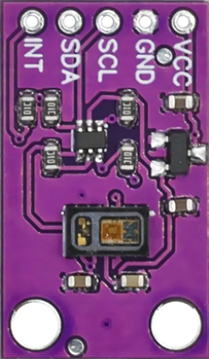
Pin Configuration and Descriptions
The MAX30105 has 14 pins, with the following configuration:
| Pin Number | Pin Name | Description |
|---|---|---|
| 1 | GND | Ground |
| 2 | SDA | I²C Data Line |
| 3 | SCL | I²C Clock Line |
| 4 | INT | Interrupt Output |
| 5 | VDD | Power Supply (1.8V core) |
| 6 | VDDIO | Power Supply (3.3V I/O) |
| 7-14 | LED1-LED6 | LED Driver Outputs |
Usage Instructions
The MAX30105 is straightforward to use in a circuit, thanks to its I²C interface and integrated components. Below are the steps and best practices for using the sensor:
Connecting the MAX30105
- Power Supply: Connect the VDD pin to a 1.8V power source and the VDDIO pin to a 3.3V power source. Ensure proper decoupling capacitors are used for stable operation.
- I²C Communication: Connect the SDA and SCL pins to the corresponding I²C lines of your microcontroller. Use pull-up resistors (typically 4.7 kΩ) on both lines.
- Interrupt Pin: The INT pin can be connected to a GPIO pin on the microcontroller to handle interrupts.
- LED Connections: The LED pins are internally connected to the sensor's driver circuitry and do not require external connections.
Example Code for Arduino UNO
The following example demonstrates how to interface the MAX30105 with an Arduino UNO to read heart rate and SpO2 data. This code uses the SparkFun MAX30105 library.
#include <Wire.h>
#include "MAX30105.h" // Include the MAX30105 library

MAX30105 particleSensor; // Create an instance of the sensor

void setup() {
  Serial.begin(9600); // Initialize serial communication
  Serial.println("Initializing MAX30105...");

  if (!particleSensor.begin()) {
    // Check if the sensor is connected and initialized
    Serial.println("MAX30105 was not found. Please check wiring/power.");
    while (1); // Halt execution if the sensor is not found
  }

  particleSensor.setup(); // Configure the sensor with default settings
  particleSensor.setPulseAmplitudeRed(0x0A); // Set red LED brightness
  particleSensor.setPulseAmplitudeIR(0x0A);  // Set IR LED brightness
}

void loop() {
  // Read data from the sensor
  long redValue = particleSensor.getRed(); // Get red LED value
  long irValue = particleSensor.getIR();   // Get IR LED value

  // Print the values to the serial monitor
  Serial.print("Red: ");
  Serial.print(redValue);
  Serial.print(" IR: ");
  Serial.println(irValue);

  delay(100); // Wait 100ms before the next reading
}
Best Practices
- Use proper decoupling capacitors (e.g., 0.1 µF and 10 µF) near the power supply pins to reduce noise.
- Avoid placing the sensor near strong light sources to minimize interference.
- Ensure the sensor is securely mounted and aligned for accurate readings.
- Use a library (e.g., SparkFun MAX30105) to simplify communication and data processing.
Troubleshooting and FAQs
Common Issues
Sensor Not Detected
- Cause: Incorrect wiring or power supply issues.
- Solution: Verify all connections, ensure proper voltage levels, and check pull-up resistors on the I²C lines.
Inaccurate Readings
- Cause: External light interference or improper sensor placement.
- Solution: Shield the sensor from ambient light and ensure it is properly aligned with the measurement site.
I²C Communication Errors
- Cause: Incorrect I²C address or clock speed.
- Solution: Confirm the sensor's I²C address (default: 0x57) and ensure the microcontroller's I²C clock speed is set to 400 kHz or lower.
FAQs
Q: Can the MAX30105 measure SpO2 directly?
A: The MAX30105 provides raw data for red and IR light absorption. SpO2 calculation requires additional signal processing, which can be implemented in software.
Q: What is the maximum I²C cable length?
A: The maximum length depends on the pull-up resistor values and the I²C clock speed. For reliable communication, keep the cable length under 1 meter.
Q: Can the MAX30105 be used for smoke detection?
A: Yes, the MAX30105 can detect particles in the air, making it suitable for smoke detection applications.
By following this documentation, users can effectively integrate the MAX30105 into their projects and troubleshoot common issues.