How to Use Energy Monitor: Examples, Pinouts, and Specs
Introduction
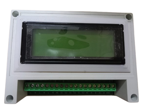
An Energy Monitor is a device designed to measure and display the amount of electrical energy consumed by a circuit or appliance. It provides real-time data on energy usage, helping users monitor consumption patterns and improve energy efficiency. These devices are commonly used in residential, commercial, and industrial settings to track power usage, reduce energy costs, and promote sustainable practices.
Explore Projects Built with Energy Monitor
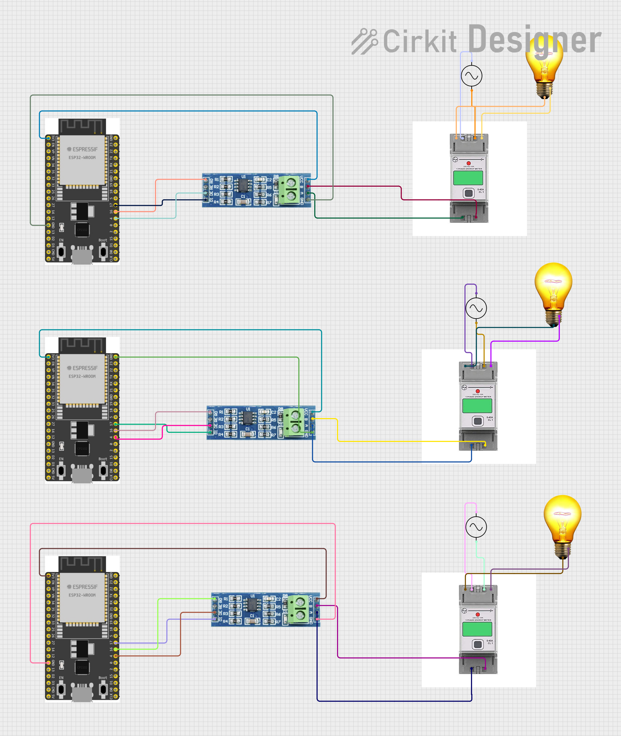

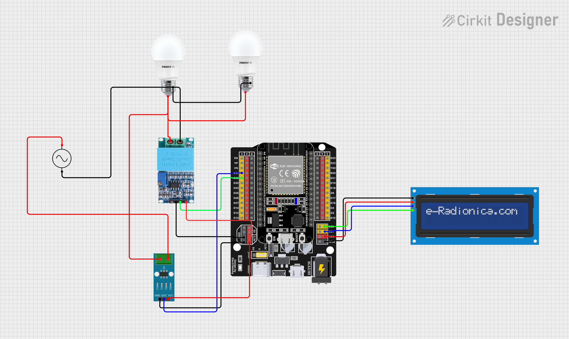
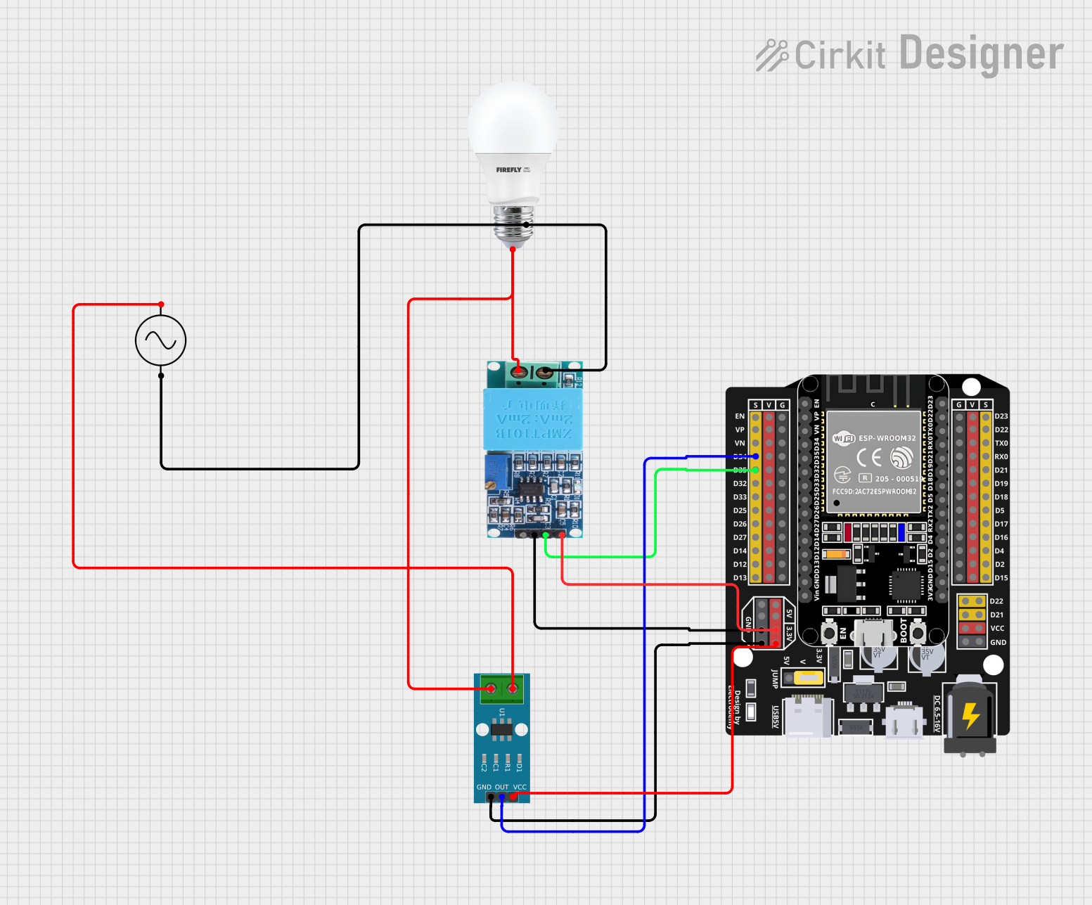
Explore Projects Built with Energy Monitor
Common Applications and Use Cases
- Monitoring household energy consumption to identify high-usage appliances.
- Industrial energy management to optimize power usage and reduce waste.
- Integration into smart home systems for automated energy tracking.
- Educational purposes to teach energy efficiency and conservation.
- Renewable energy systems to measure energy production and consumption.
Technical Specifications
Below are the general technical specifications for a typical energy monitor. Specific models may vary, so always refer to the manufacturer's datasheet for precise details.
Key Specifications
- Input Voltage Range: 100V to 240V AC
- Current Measurement Range: 0A to 100A (depending on the current sensor used)
- Power Measurement Accuracy: ±1% (typical)
- Frequency Range: 50Hz to 60Hz
- Communication Interface: UART, I2C, or SPI (varies by model)
- Power Supply: 5V DC (for digital energy monitors)
- Display: LCD or LED (optional, depending on the model)
Pin Configuration and Descriptions
The pin configuration for a digital energy monitor module is as follows:
| Pin Name | Description |
|---|---|
| VCC | Power supply input (typically 5V DC). |
| GND | Ground connection. |
| SCL | Serial Clock Line for I2C communication. |
| SDA | Serial Data Line for I2C communication. |
| TX | Transmit pin for UART communication (if applicable). |
| RX | Receive pin for UART communication (if applicable). |
| CT+ | Positive terminal for the current transformer (CT) sensor. |
| CT- | Negative terminal for the current transformer (CT) sensor. |
| AC+ | Positive terminal for AC voltage input (used for voltage measurement). |
| AC- | Negative terminal for AC voltage input (used for voltage measurement). |
Usage Instructions
How to Use the Energy Monitor in a Circuit
- Connect the Power Supply:
- Provide a stable 5V DC power supply to the
VCCandGNDpins.
- Provide a stable 5V DC power supply to the
- Connect the Current Transformer (CT) Sensor:
- Attach the CT sensor to the
CT+andCT-pins. Ensure the CT sensor is clamped around the live wire of the circuit you want to monitor.
- Attach the CT sensor to the
- Connect the Voltage Input:
- Connect the
AC+andAC-pins to the AC voltage source. Use proper isolation and safety precautions when working with high voltages.
- Connect the
- Establish Communication:
- For I2C communication, connect the
SCLandSDApins to the corresponding pins on your microcontroller (e.g., Arduino). - For UART communication, connect the
TXandRXpins to the microcontroller's UART pins.
- For I2C communication, connect the
- Read Data:
- Use the appropriate library or communication protocol to read energy consumption data from the energy monitor.
Important Considerations and Best Practices
- Safety First: Always ensure proper insulation and isolation when working with high-voltage AC circuits.
- Calibration: Some energy monitors require calibration to ensure accurate readings. Follow the manufacturer's instructions for calibration.
- Current Sensor Placement: Ensure the CT sensor is clamped around only one conductor (live or neutral) and not both, as this will result in incorrect readings.
- Avoid Overloading: Do not exceed the maximum current and voltage ratings of the energy monitor.
Example: Using an Energy Monitor with Arduino UNO
Below is an example of how to interface an energy monitor with an Arduino UNO using I2C communication.
#include <Wire.h> // Include the Wire library for I2C communication

#define ENERGY_MONITOR_ADDRESS 0x40 // Replace with the actual I2C address of your energy monitor

void setup() {
  Serial.begin(9600); // Initialize serial communication for debugging
  Wire.begin();       // Initialize I2C communication
  Serial.println("Energy Monitor Initialized");
}

void loop() {
  Wire.beginTransmission(ENERGY_MONITOR_ADDRESS); // Start communication with the energy monitor
  Wire.write(0x00); // Request data (register address may vary by model)
  Wire.endTransmission();

  Wire.requestFrom(ENERGY_MONITOR_ADDRESS, 4); // Request 4 bytes of data
  if (Wire.available() == 4) {
    // Read the energy data (example: power in watts)
    uint16_t power = Wire.read() << 8 | Wire.read(); // Combine two bytes into a 16-bit value
    uint16_t voltage = Wire.read() << 8 | Wire.read(); // Combine two bytes into a 16-bit value

    // Print the readings to the serial monitor
    Serial.print("Power: ");
    Serial.print(power);
    Serial.print(" W, Voltage: ");
    Serial.print(voltage);
    Serial.println(" V");
  }

  delay(1000); // Wait for 1 second before the next reading
}
Troubleshooting and FAQs
Common Issues and Solutions
No Data Output:
- Cause: Incorrect wiring or communication protocol mismatch.
- Solution: Double-check the connections and ensure the correct communication protocol (I2C, UART, etc.) is used.
Inaccurate Readings:
- Cause: Improper calibration or incorrect CT sensor placement.
- Solution: Follow the calibration procedure provided by the manufacturer. Ensure the CT sensor is clamped around a single conductor.
Energy Monitor Not Powering On:
- Cause: Insufficient or incorrect power supply.
- Solution: Verify that the
VCCpin is receiving a stable 5V DC supply.
Overheating:
- Cause: Exceeding the maximum current or voltage ratings.
- Solution: Ensure the monitored circuit does not exceed the energy monitor's rated specifications.
FAQs
Q: Can I use the energy monitor with a 3.3V microcontroller?
- A: Yes, but ensure the energy monitor supports 3.3V logic levels or use a level shifter.
Q: How do I calculate energy consumption over time?
- A: Multiply the power reading (in watts) by the time (in hours) to get energy consumption in watt-hours (Wh).
Q: Can I monitor multiple circuits with one energy monitor?
- A: No, each energy monitor is designed to measure a single circuit. Use multiple monitors for multiple circuits.
Q: Is it safe to use the energy monitor with high-voltage appliances?
- A: Yes, but always follow safety guidelines and use proper insulation and isolation techniques.