
How to Use 74HC139: Examples, Pinouts, and Specs
 Design with 74HC139 in Cirkit Designer
Introduction
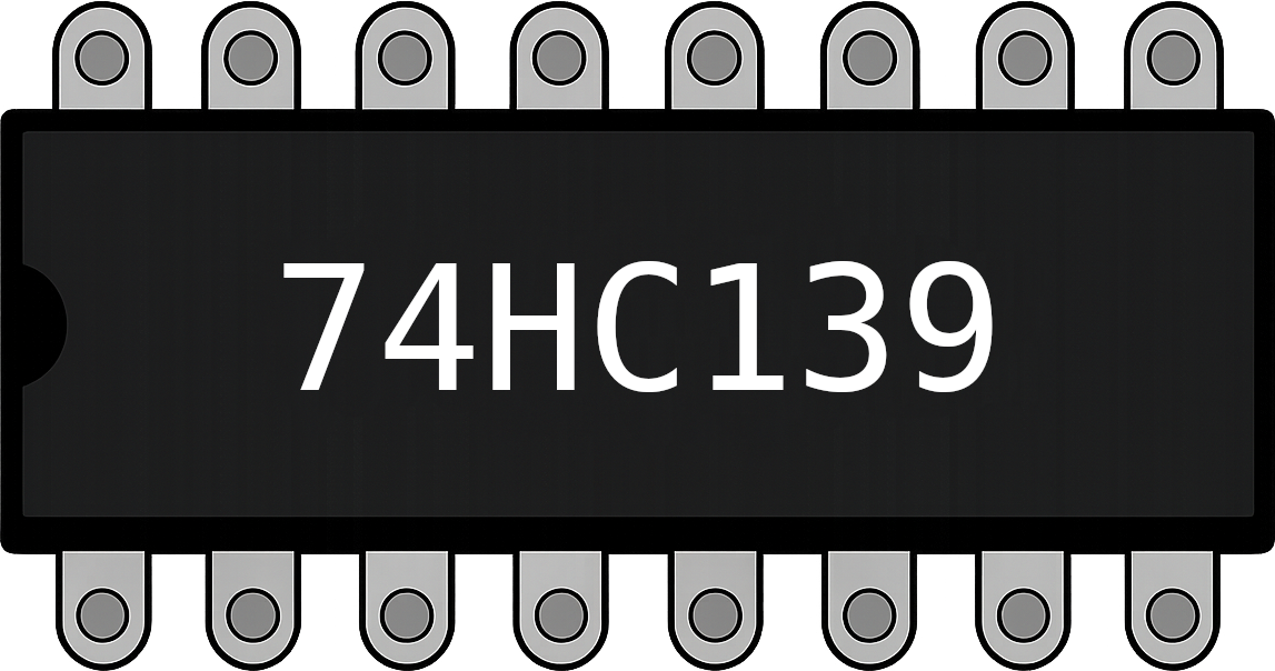
The 74HC139 is a high-speed CMOS dual 2-to-4 line decoder/demultiplexer. It is designed to convert binary inputs into a single active low output. This IC contains two independent decoders, each with two binary inputs and four mutually exclusive outputs. The 74HC139 is widely used in digital circuits for tasks such as address decoding, data routing, and signal demultiplexing.
Explore Projects Built with 74HC139
 Open Project in Cirkit Designer
 Open Project in Cirkit Designer
 Open Project in Cirkit Designer
 Open Project in Cirkit Designer
Explore Projects Built with 74HC139
Open Project in Cirkit DesignerOpen Project in Cirkit DesignerOpen Project in Cirkit DesignerOpen Project in Cirkit DesignerCommon Applications
- Address decoding in memory systems
- Data routing in digital systems
- Signal demultiplexing
- Logic signal generation
- Control signal distribution in microcontroller-based systems
Technical Specifications
The 74HC139 is a versatile and reliable component with the following key specifications:
| Parameter | Value |
|---|---|
| Supply Voltage (Vcc) | 2V to 6V |
| Input Voltage Range | 0V to Vcc |
| Output Current (per pin) | ±5.2 mA |
| Maximum Power Dissipation | 500 mW |
| Propagation Delay | ~16 ns at Vcc = 5V |
| Operating Temperature | -40°C to +125°C |
| Package Types | DIP-16, SOIC-16, TSSOP-16 |
Pin Configuration and Descriptions
The 74HC139 comes in a 16-pin package. Below is the pinout and description:
| Pin Number | Pin Name | Description |
|---|---|---|
| 1 | G1 | Enable input for decoder 1 (active low) |
| 2 | A1 | Input A for decoder 1 |
| 3 | B1 | Input B for decoder 1 |
| 4 | Y0_1 | Output 0 for decoder 1 (active low) |
| 5 | Y1_1 | Output 1 for decoder 1 (active low) |
| 6 | Y2_1 | Output 2 for decoder 1 (active low) |
| 7 | Y3_1 | Output 3 for decoder 1 (active low) |
| 8 | GND | Ground |
| 9 | Y3_2 | Output 3 for decoder 2 (active low) |
| 10 | Y2_2 | Output 2 for decoder 2 (active low) |
| 11 | Y1_2 | Output 1 for decoder 2 (active low) |
| 12 | Y0_2 | Output 0 for decoder 2 (active low) |
| 13 | A2 | Input A for decoder 2 |
| 14 | B2 | Input B for decoder 2 |
| 15 | G2 | Enable input for decoder 2 (active low) |
| 16 | Vcc | Positive supply voltage |
Usage Instructions
How to Use the 74HC139 in a Circuit
- Power Supply: Connect the Vcc pin (pin 16) to a voltage source between 2V and 6V, and the GND pin (pin 8) to ground.
- Enable Inputs: Each decoder has an enable input (G1 for decoder 1 and G2 for decoder 2). These inputs must be set to logic LOW to activate the corresponding decoder.
- Binary Inputs: Provide binary inputs to A1 and B1 for decoder 1, and A2 and B2 for decoder 2. These inputs determine which output pin will be active (LOW).
- Outputs: The outputs (Y0 to Y3 for each decoder) are active LOW. Only one output will be LOW at a time, based on the binary input combination.
Truth Table for Each Decoder
| G (Enable) | B | A | Y0 | Y1 | Y2 | Y3 |
|---|---|---|---|---|---|---|
| 1 | X | X | 1 | 1 | 1 | 1 |
| 0 | 0 | 0 | 0 | 1 | 1 | 1 |
| 0 | 0 | 1 | 1 | 0 | 1 | 1 |
| 0 | 1 | 0 | 1 | 1 | 0 | 1 |
| 0 | 1 | 1 | 1 | 1 | 1 | 0 |
Example: Connecting the 74HC139 to an Arduino UNO
The 74HC139 can be easily interfaced with an Arduino UNO for address decoding or signal routing. Below is an example of how to control one of the decoders:
Circuit Connections
- Connect Vcc (pin 16) to the Arduino's 5V pin.
- Connect GND (pin 8) to the Arduino's GND.
- Connect A1 (pin 2) and B1 (pin 3) to Arduino digital pins 2 and 3, respectively.
- Connect G1 (pin 1) to Arduino digital pin 4.
- Connect the outputs (Y0_1 to Y3_1) to LEDs or other devices.
Arduino Code
// Define pins for the 74HC139
const int enablePin = 4; // G1 (Enable for decoder 1)
const int inputA = 2;    // A1 (Input A for decoder 1)
const int inputB = 3;    // B1 (Input B for decoder 1)

void setup() {
  // Set pin modes
  pinMode(enablePin, OUTPUT);
  pinMode(inputA, OUTPUT);
  pinMode(inputB, OUTPUT);

  // Enable the decoder by setting G1 to LOW
  digitalWrite(enablePin, LOW);
}

void loop() {
  // Example: Cycle through all outputs
  for (int i = 0; i < 4; i++) {
    digitalWrite(inputA, i & 0x01); // Set A1 based on LSB of i
    digitalWrite(inputB, (i >> 1) & 0x01); // Set B1 based on MSB of i
    delay(1000); // Wait 1 second before switching
  }
}
Important Considerations
- Ensure that the enable pins (G1 and G2) are set LOW to activate the decoders.
- Avoid exceeding the maximum voltage and current ratings to prevent damage.
- Use pull-up or pull-down resistors on unused inputs to avoid floating states.
Troubleshooting and FAQs
Common Issues
No Output is Active:
- Ensure the enable pin (G1 or G2) is set to logic LOW.
- Verify that the power supply is connected properly.
Incorrect Output:
- Check the binary input connections (A and B) for loose or incorrect wiring.
- Verify the truth table to ensure the correct input-output mapping.
All Outputs are HIGH:
- Confirm that the enable pin is not floating or set to HIGH.
- Check for damaged IC or incorrect power supply voltage.
FAQs
Q: Can I use the 74HC139 with a 3.3V microcontroller?
A: Yes, the 74HC139 operates with a supply voltage as low as 2V, making it compatible with 3.3V systems.
Q: What happens if both decoders are enabled simultaneously?
A: Each decoder operates independently, so enabling both will not cause interference. However, ensure proper input signals to avoid conflicts.
Q: Can the outputs drive LEDs directly?
A: Yes, but ensure the current does not exceed the maximum output current rating (±5.2 mA per pin). Use current-limiting resistors for LEDs.