How to Use Autopilot: Examples, Pinouts, and Specs
Introduction
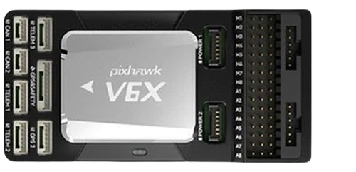
The CUAV V6X Autopilot is a high-performance flight control system designed to automate the trajectory of vehicles such as aircraft, drones, and spacecraft. It enables precise navigation and control without requiring constant manual input from a pilot. The V6X is equipped with advanced sensors, processing capabilities, and communication interfaces, making it suitable for a wide range of applications, including unmanned aerial vehicles (UAVs), autonomous delivery systems, and research platforms.
Explore Projects Built with Autopilot
Explore Projects Built with Autopilot
Common Applications and Use Cases
- Unmanned Aerial Vehicles (UAVs): Used in drones for mapping, surveillance, and delivery.
- Autonomous Aircraft: Enables self-piloting capabilities for experimental or commercial aircraft.
- Spacecraft Navigation: Assists in trajectory control for satellites and space exploration vehicles.
- Agricultural Drones: Automates crop monitoring and spraying tasks.
- Search and Rescue Operations: Provides reliable navigation in challenging environments.
Technical Specifications
The CUAV V6X Autopilot is built to meet the demands of modern autonomous systems. Below are its key technical details:
Key Technical Details
- Processor: STM32H7 series high-performance microcontroller
- IMU (Inertial Measurement Unit): Triple redundant IMUs for enhanced reliability
- Barometer: Dual redundant barometers for altitude measurement
- Input Voltage Range: 4.5V to 5.5V
- Communication Interfaces: CAN, UART, I2C, SPI, USB
- GPS Support: External GPS module compatibility
- Operating Temperature Range: -20°C to 60°C
- Dimensions: 72mm x 44mm x 16mm
- Weight: 38g
Pin Configuration and Descriptions
The CUAV V6X features multiple connectors for interfacing with peripherals. Below is the pin configuration:
Power and Communication Ports
| Port Name | Pin | Description |
|---|---|---|
| Power Input | VCC | 4.5V to 5.5V input for powering the unit |
| GND | Ground connection | |
| CAN Port | CAN_H | CAN bus high signal |
| CAN_L | CAN bus low signal | |
| UART Port | TX | UART transmit signal |
| RX | UART receive signal |
Peripheral Interfaces
| Port Name | Pin | Description |
|---|---|---|
| I2C Port | SDA | I2C data line |
| SCL | I2C clock line | |
| SPI Port | MISO | SPI master-in/slave-out |
| MOSI | SPI master-out/slave-in | |
| SCK | SPI clock signal | |
| CS | SPI chip select | |
| GPS Port | TX | GPS transmit signal |
| RX | GPS receive signal |
Usage Instructions
The CUAV V6X Autopilot is designed to integrate seamlessly into autonomous systems. Follow the steps below to use it effectively:
Step 1: Powering the Autopilot
- Connect a regulated power supply (4.5V to 5.5V) to the Power Input pins.
- Ensure proper grounding to avoid electrical noise or damage.
Step 2: Connecting Peripherals
- Attach sensors (e.g., GPS, barometer) to the appropriate ports (e.g., GPS Port, I2C Port).
- Use the CAN or UART ports to interface with external communication modules.
Step 3: Configuring the Autopilot
- Install the appropriate firmware (e.g., PX4 or ArduPilot) using the USB interface.
- Use a ground control station (e.g., QGroundControl or Mission Planner) to configure flight parameters.
Step 4: Testing and Calibration
- Perform sensor calibration (e.g., IMU, compass) through the ground control station.
- Conduct a bench test to verify all connections and functionality before deployment.
Step 5: Deploying in a Vehicle
- Mount the V6X securely in the vehicle, ensuring minimal vibration.
- Connect the autopilot to the vehicle's power distribution system and actuators (e.g., motors, servos).
Arduino UNO Example Code
The CUAV V6X can communicate with an Arduino UNO via UART. Below is an example code snippet for reading data from the autopilot:
#include <SoftwareSerial.h>

// Define RX and TX pins for UART communication
SoftwareSerial autopilotSerial(10, 11); // RX = pin 10, TX = pin 11

void setup() {
  // Initialize serial communication with the autopilot
  autopilotSerial.begin(57600); // Set baud rate to 57600
  Serial.begin(9600);           // For debugging via Serial Monitor

  Serial.println("Autopilot communication initialized.");
}

void loop() {
  // Check if data is available from the autopilot
  if (autopilotSerial.available()) {
    String data = autopilotSerial.readString(); // Read incoming data
    Serial.println("Received from Autopilot: " + data); // Print to Serial Monitor
  }

  delay(100); // Small delay to avoid flooding the Serial Monitor
}
Important Considerations and Best Practices
- Power Supply: Use a stable power source to prevent voltage fluctuations.
- Firmware Updates: Regularly update the firmware to access new features and bug fixes.
- Vibration Isolation: Use vibration-dampening mounts to improve sensor accuracy.
- Pre-Flight Checks: Always perform a pre-flight checklist to ensure system readiness.
Troubleshooting and FAQs
Common Issues and Solutions
Autopilot Not Powering On
- Cause: Insufficient or unstable power supply.
- Solution: Verify the input voltage is within the 4.5V to 5.5V range and check connections.
No Communication with Ground Control Station
- Cause: Incorrect USB driver or baud rate settings.
- Solution: Install the correct USB driver and ensure the baud rate matches the configuration.
Inaccurate Sensor Readings
- Cause: Vibration or improper calibration.
- Solution: Use vibration-dampening mounts and recalibrate the sensors.
Vehicle Not Following Planned Trajectory
- Cause: Incorrect flight parameters or GPS signal loss.
- Solution: Verify flight parameters and ensure the GPS module has a clear view of the sky.
FAQs
Q: Can the V6X be used with fixed-wing aircraft?
A: Yes, the V6X supports fixed-wing, multirotor, and VTOL configurations.Q: What firmware is compatible with the V6X?
A: The V6X supports PX4 and ArduPilot firmware.Q: How do I update the firmware?
A: Use the USB interface and a ground control station like QGroundControl to upload the latest firmware.Q: Can I use multiple GPS modules with the V6X?
A: Yes, the V6X supports dual GPS modules for redundancy and improved accuracy.
By following this documentation, users can effectively integrate and operate the CUAV V6X Autopilot in their autonomous systems.