
How to Use Cyberbrick RX: Examples, Pinouts, and Specs
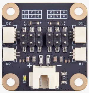
 Design with Cyberbrick RX in Cirkit Designer
Introduction
The Cyberbrick RX, manufactured by MakerWorld, is a versatile, programmable microcontroller designed specifically for robotics and automation projects. It combines multiple input/output (I/O) ports, built-in sensors, and wireless communication capabilities, making it an excellent choice for creating smart devices and interactive systems. Its robust design and flexibility allow it to be used in a wide range of applications, from educational robotics to advanced home automation systems.
Explore Projects Built with Cyberbrick RX
 Open Project in Cirkit Designer
 Open Project in Cirkit Designer
 Open Project in Cirkit Designer
 Open Project in Cirkit Designer
Explore Projects Built with Cyberbrick RX
Open Project in Cirkit DesignerOpen Project in Cirkit DesignerOpen Project in Cirkit DesignerOpen Project in Cirkit DesignerCommon Applications
- Robotics and autonomous vehicles
- Smart home devices and IoT systems
- Industrial automation and control systems
- Educational projects and prototyping
- Interactive art installations
Technical Specifications
Key Technical Details
| Specification | Value |
|---|---|
| Microcontroller | 32-bit ARM Cortex-M4 |
| Operating Voltage | 3.3V |
| Input Voltage Range | 5V - 12V |
| Digital I/O Pins | 16 (PWM capable: 8 pins) |
| Analog Input Pins | 6 (12-bit ADC resolution) |
| Communication Interfaces | UART, I2C, SPI, Bluetooth 5.0, Wi-Fi |
| Built-in Sensors | Temperature, Accelerometer, Gyroscope |
| Flash Memory | 512 KB |
| SRAM | 128 KB |
| Clock Speed | 72 MHz |
| Power Consumption | 50 mA (typical) |
| Dimensions | 50mm x 30mm x 10mm |
Pin Configuration and Descriptions
| Pin Number | Pin Name | Description |
|---|---|---|
| 1 | VIN | Input voltage (5V - 12V) |
| 2 | GND | Ground |
| 3 | 3V3 | 3.3V output |
| 4 | D0 (RX) | Digital I/O, UART RX |
| 5 | D1 (TX) | Digital I/O, UART TX |
| 6 | D2 | Digital I/O |
| 7 | D3 (PWM) | Digital I/O, PWM capable |
| 8 | D4 | Digital I/O |
| 9 | D5 (PWM) | Digital I/O, PWM capable |
| 10 | D6 (PWM) | Digital I/O, PWM capable |
| 11 | D7 | Digital I/O |
| 12 | A0 | Analog input |
| 13 | A1 | Analog input |
| 14 | SDA | I2C Data |
| 15 | SCL | I2C Clock |
| 16 | RST | Reset |
Usage Instructions
How to Use the Cyberbrick RX in a Circuit
Powering the Cyberbrick RX:
Connect the VIN pin to a power source (5V - 12V) and the GND pin to ground. Alternatively, you can power the device via the micro-USB port.Connecting Sensors and Actuators:
Use the digital I/O pins (D0-D7) for connecting sensors, LEDs, or actuators. For analog sensors, connect them to the analog input pins (A0-A5).Programming the Cyberbrick RX:
The Cyberbrick RX can be programmed using the Arduino IDE or other compatible platforms. Select the appropriate board and port in the IDE, write your code, and upload it via the micro-USB connection.Wireless Communication:
Utilize the built-in Bluetooth or Wi-Fi modules for wireless communication. Libraries for these modules are available in the Arduino IDE.
Important Considerations and Best Practices
- Ensure the input voltage does not exceed 12V to avoid damaging the microcontroller.
- Use appropriate pull-up or pull-down resistors for I/O pins when necessary.
- Avoid drawing more than 50 mA from the 3.3V output pin.
- For wireless communication, ensure the device is within the recommended range for Bluetooth or Wi-Fi.
Example Code for Arduino UNO Integration
Below is an example of how to use the Cyberbrick RX with an Arduino UNO to read temperature data from the built-in sensor and send it via Bluetooth.
#include <SoftwareSerial.h>

// Define RX and TX pins for Bluetooth communication
SoftwareSerial bluetooth(10, 11); // RX, TX

void setup() {
  Serial.begin(9600); // Initialize serial communication for debugging
  bluetooth.begin(9600); // Initialize Bluetooth communication

  // Print a message to indicate the system is ready
  Serial.println("Cyberbrick RX is ready!");
}

void loop() {
  // Simulate reading temperature from the built-in sensor
  float temperature = readTemperature();

  // Send temperature data via Bluetooth
  bluetooth.print("Temperature: ");
  bluetooth.print(temperature);
  bluetooth.println(" °C");

  // Wait for 1 second before sending the next reading
  delay(1000);
}

// Function to simulate reading temperature from the built-in sensor
float readTemperature() {
  // Replace this with actual sensor reading logic if available
  return 25.0 + random(-5, 5) * 0.1; // Simulated temperature value
}
Troubleshooting and FAQs
Common Issues and Solutions
The Cyberbrick RX is not powering on:
- Ensure the input voltage is within the 5V - 12V range.
- Check the power connections and ensure the GND pin is properly connected.
Unable to upload code to the Cyberbrick RX:
- Verify that the correct board and port are selected in the Arduino IDE.
- Ensure the micro-USB cable is functional and supports data transfer.
- Press the reset button on the Cyberbrick RX before uploading the code.
Wireless communication is not working:
- Check if the Bluetooth or Wi-Fi module is enabled in your code.
- Ensure the device is within range and there are no significant obstacles.
- Verify the baud rate and other communication settings.
FAQs
Q: Can I use the Cyberbrick RX with a 5V sensor?
A: Yes, the Cyberbrick RX is compatible with 5V sensors. However, ensure proper voltage level shifting if needed for communication lines.
Q: What is the maximum range for Bluetooth communication?
A: The Bluetooth 5.0 module on the Cyberbrick RX supports a range of up to 100 meters in open space.
Q: Can I use the Cyberbrick RX for battery-powered projects?
A: Yes, the Cyberbrick RX can be powered using a battery pack within the 5V - 12V range. Ensure the battery capacity is sufficient for your project’s power requirements.