How to Use Noctua PWM FAN: Examples, Pinouts, and Specs
Introduction
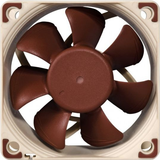
The Noctua PWM FAN is a high-performance cooling fan designed for use in computer systems and other electronic applications requiring efficient heat dissipation. Utilizing Pulse Width Modulation (PWM) technology, this fan allows precise speed control, enabling optimal cooling performance while maintaining low noise levels. Known for its durability and reliability, the Noctua PWM FAN is a popular choice among PC enthusiasts, system builders, and engineers.
Explore Projects Built with Noctua PWM FAN
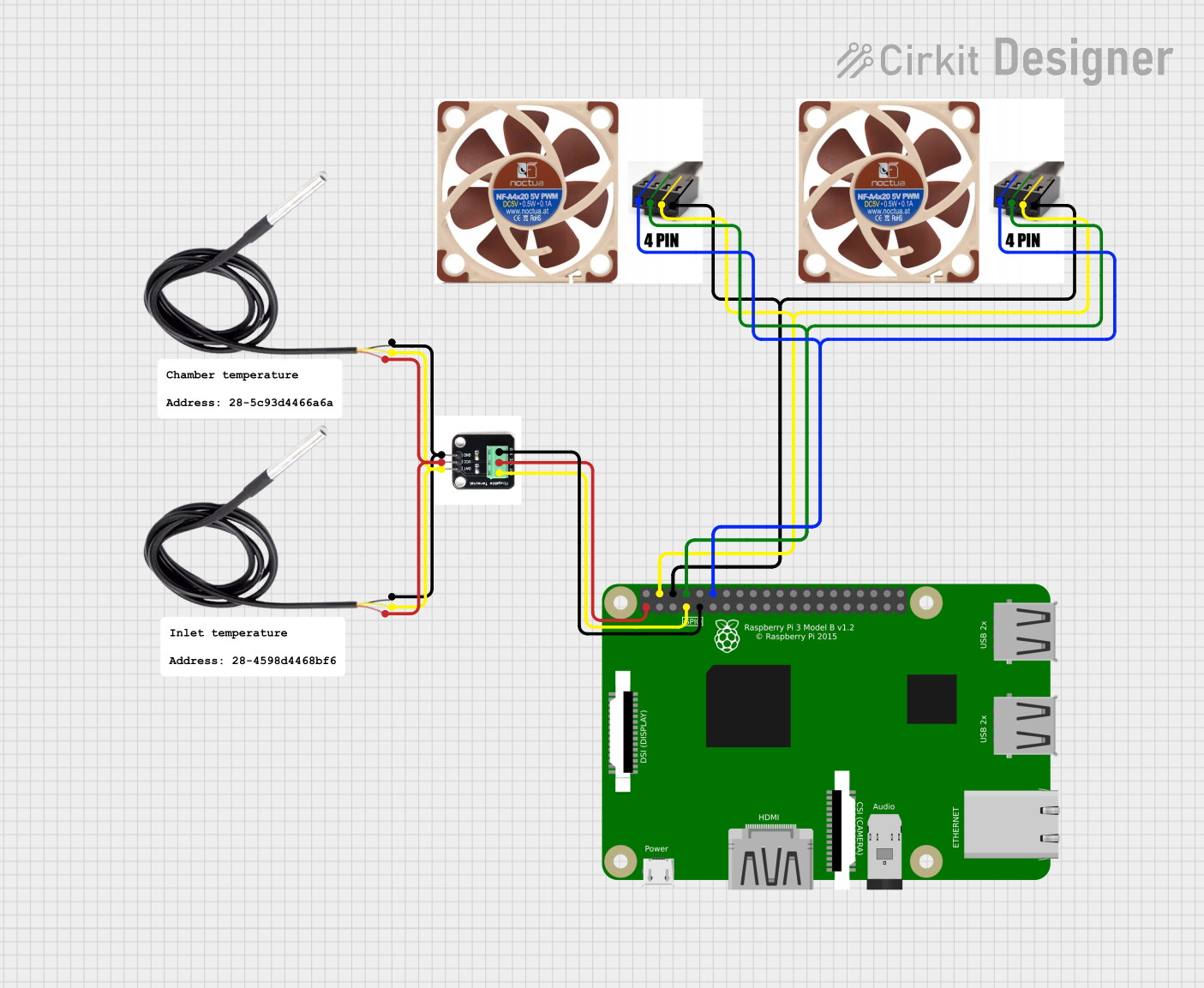
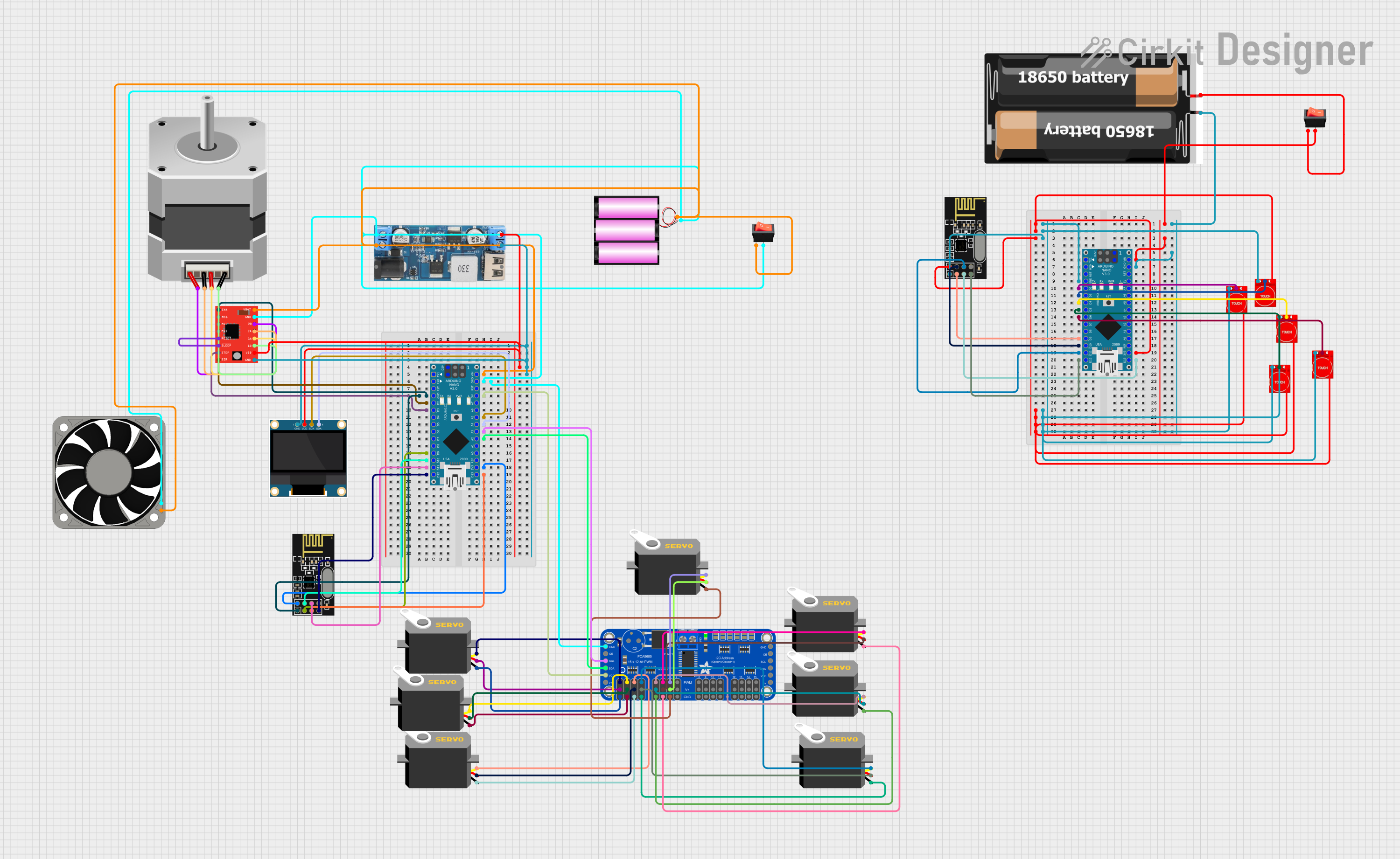
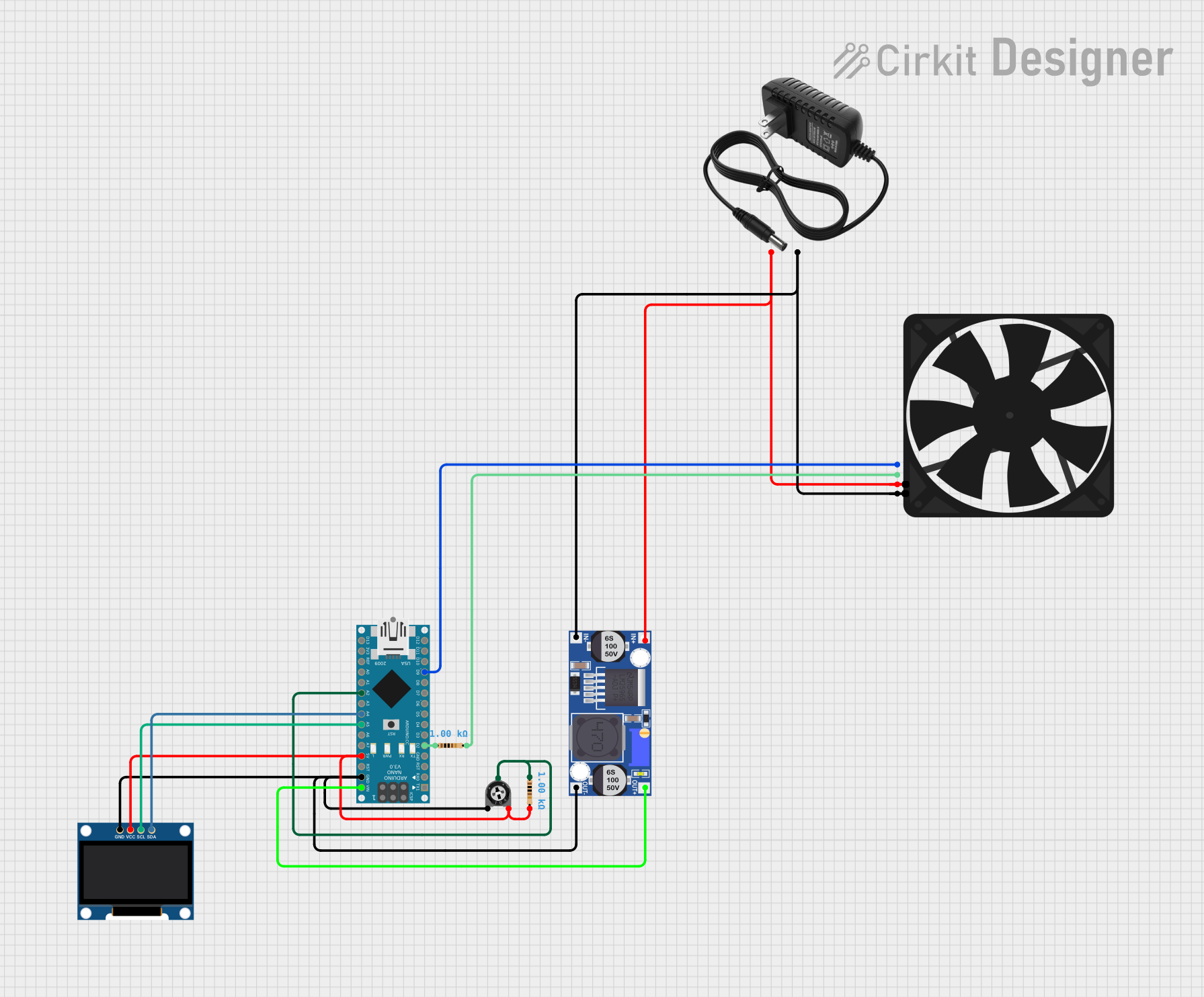

Explore Projects Built with Noctua PWM FAN
Common Applications and Use Cases
- Cooling for computer CPUs, GPUs, and cases
- Heat dissipation in power supplies and electronic enclosures
- Custom cooling solutions for robotics and embedded systems
- Noise-sensitive environments requiring quiet operation
Technical Specifications
The Noctua PWM FAN is available in various models, each with slightly different specifications. Below are the general technical details for a typical Noctua PWM FAN:
| Parameter | Specification |
|---|---|
| Operating Voltage Range | 12V DC ± 10% |
| Rated Current | 0.05A to 0.15A (varies by model) |
| Power Consumption | 0.6W to 1.8W (varies by model) |
| Fan Speed Range | 300 RPM to 2000 RPM (PWM controlled) |
| Airflow | Up to 70 CFM (varies by model) |
| Noise Level | 18 dBA to 25 dBA (varies by model) |
| Connector Type | 4-pin PWM |
| Bearing Type | SSO2 (Self-Stabilizing Oil Pressure) |
| Lifespan | >150,000 hours (MTTF) |
Pin Configuration and Descriptions
The Noctua PWM FAN uses a standard 4-pin connector for power and control. The pinout is as follows:
| Pin Number | Name | Description |
|---|---|---|
| 1 | GND | Ground connection for the fan motor |
| 2 | +12V | Positive power supply for the fan motor |
| 3 | Sense | Tachometer output for monitoring fan speed (provides 2 pulses per revolution) |
| 4 | PWM | Pulse Width Modulation input for speed control (active high, 25 kHz frequency) |
Usage Instructions
How to Use the Noctua PWM FAN in a Circuit
- Power Connection: Connect the GND pin to the ground of your power supply and the +12V pin to a 12V DC power source.
- Speed Control: Use a PWM signal (25 kHz frequency) on the PWM pin to control the fan speed. A duty cycle of 0% stops the fan, while 100% runs it at full speed.
- Speed Monitoring: Connect the Sense pin to a microcontroller or monitoring circuit to measure the fan's RPM.
Important Considerations and Best Practices
- Ensure the power supply provides a stable 12V DC output within the specified voltage range.
- Use a PWM signal generator or a microcontroller (e.g., Arduino) to control the fan speed.
- Avoid blocking the fan's airflow to maintain optimal cooling performance.
- Mount the fan securely to minimize vibrations and noise.
- If using the fan in a dusty environment, clean it periodically to prevent dust buildup.
Example: Connecting the Noctua PWM FAN to an Arduino UNO
Below is an example of how to control the Noctua PWM FAN using an Arduino UNO:
// Example: Controlling Noctua PWM FAN with Arduino UNO
// This code generates a PWM signal to control the fan speed.

const int pwmPin = 9; // PWM pin connected to the fan's PWM input

void setup() {
  pinMode(pwmPin, OUTPUT); // Set the PWM pin as an output
}

void loop() {
  // Set fan speed to 50% (128 out of 255)
  analogWrite(pwmPin, 128);
  delay(5000); // Run at 50% speed for 5 seconds

  // Set fan speed to 100% (255 out of 255)
  analogWrite(pwmPin, 255);
  delay(5000); // Run at full speed for 5 seconds

  // Set fan speed to 0% (0 out of 255)
  analogWrite(pwmPin, 0);
  delay(5000); // Stop the fan for 5 seconds
}
Notes:
- The
analogWrite()function generates a PWM signal on the specified pin. - Ensure the Arduino's ground is connected to the fan's ground (GND pin).
- Use an external 12V power supply for the fan, as the Arduino cannot provide sufficient power.
Troubleshooting and FAQs
Common Issues and Solutions
Fan Does Not Spin
- Cause: No power or incorrect wiring.
- Solution: Verify the GND and +12V connections. Ensure the power supply is functioning and within the specified voltage range.
Fan Spins at Full Speed Constantly
- Cause: PWM signal not connected or incorrect frequency.
- Solution: Check the PWM connection and ensure the signal is at 25 kHz. Use a microcontroller or PWM generator to provide the correct signal.
Fan Speed Cannot Be Controlled
- Cause: Incorrect PWM duty cycle or incompatible controller.
- Solution: Verify the PWM duty cycle (0% to 100%) and ensure the controller supports 4-pin PWM fans.
High Noise Levels
- Cause: Obstructed airflow or loose mounting.
- Solution: Ensure the fan is mounted securely and there are no obstructions in the airflow path.
FAQs
Can I use the Noctua PWM FAN with a 3-pin connector?
- Yes, but you will lose PWM speed control. The fan will run at full speed when connected to a 3-pin header.
What is the recommended PWM frequency?
- The recommended PWM frequency is 25 kHz for optimal performance.
Can I use the fan with a lower voltage (e.g., 5V)?
- No, the fan is designed to operate at 12V DC. Using a lower voltage may prevent it from starting or reduce performance.
How do I clean the fan?
- Use compressed air to remove dust from the blades and housing. Avoid using water or harsh chemicals.
By following this documentation, you can effectively integrate the Noctua PWM FAN into your projects for efficient and quiet cooling.