How to Use Rcd switch: Examples, Pinouts, and Specs
Introduction
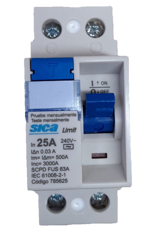
A Residual Current Device (RCD) switch is a critical safety component in electrical systems. It is designed to protect users from electric shocks and prevent electrical fires by disconnecting the power supply when it detects an imbalance between the live and neutral currents. This imbalance typically indicates a leakage current, which could be caused by a fault or accidental contact with a live wire.
Explore Projects Built with Rcd switch


Explore Projects Built with Rcd switch
Common Applications and Use Cases
- Residential Electrical Systems: Protects household circuits and appliances.
- Industrial Environments: Ensures worker safety in high-power equipment setups.
- Outdoor Installations: Provides protection for garden equipment, outdoor lighting, and power tools.
- Portable Devices: Used in portable power distribution units for added safety.
Technical Specifications
The RCD switch is available in various configurations depending on the application. Below are the general technical specifications:
| Parameter | Value |
|---|---|
| Rated Voltage | 230V AC (single-phase) or 400V AC (three-phase) |
| Rated Current | 16A, 32A, 63A (varies by model) |
| Rated Residual Current | 10mA, 30mA, 100mA, or 300mA |
| Operating Frequency | 50Hz/60Hz |
| Trip Time | ≤ 300ms (standard) |
| Number of Poles | 2P (single-phase) or 4P (three-phase) |
| Operating Temperature | -25°C to +55°C |
| Mounting Type | DIN rail |
| Compliance Standards | IEC 61008, IEC 61009 |
Pin Configuration and Descriptions
The RCD switch typically has the following terminals:
| Terminal | Description |
|---|---|
| L (Line) | Connects to the live wire of the power supply. |
| N (Neutral) | Connects to the neutral wire of the power supply. |
| Load L | Connects to the live wire of the load (output). |
| Load N | Connects to the neutral wire of the load (output). |
Usage Instructions
How to Use the RCD Switch in a Circuit
- Identify the Power Supply: Ensure the RCD switch is rated for the voltage and current of your circuit.
- Connect the Input Terminals:
- Connect the live wire of the power supply to the L (Line) terminal.
- Connect the neutral wire of the power supply to the N (Neutral) terminal.
- Connect the Output Terminals:
- Connect the live wire of the load to the Load L terminal.
- Connect the neutral wire of the load to the Load N terminal.
- Test the RCD:
- Press the "Test" button on the RCD switch to ensure it trips correctly. This simulates a leakage current and verifies the device's functionality.
- Power On: Once all connections are secure, turn on the power supply.
Important Considerations and Best Practices
- Select the Correct Rating: Choose an RCD with a residual current rating suitable for your application (e.g., 30mA for personal protection, 100mA for fire prevention).
- Regular Testing: Test the RCD switch monthly using the built-in "Test" button to ensure it is functioning properly.
- Avoid Overloading: Ensure the connected load does not exceed the rated current of the RCD.
- Proper Grounding: Ensure the circuit is properly grounded to enhance safety and effectiveness.
- Installation by Professionals: For high-voltage or complex systems, have the RCD installed by a qualified electrician.
Arduino Integration
While RCD switches are not typically controlled by microcontrollers like Arduino, they can be monitored for tripping events. For example, you can use a current sensor to detect when the RCD has tripped and trigger an alert. Below is an example of Arduino code to monitor an RCD switch using a current sensor:
// Example: Monitoring RCD trip status using a current sensor
// Connect the current sensor output to Arduino analog pin A0

const int sensorPin = A0;  // Analog pin connected to the current sensor
const int threshold = 10; // Threshold for detecting current (adjust as needed)

void setup() {
  Serial.begin(9600); // Initialize serial communication
  pinMode(sensorPin, INPUT); // Set sensor pin as input
}

void loop() {
  int sensorValue = analogRead(sensorPin); // Read current sensor value
  if (sensorValue < threshold) {
    // If current is below threshold, RCD may have tripped
    Serial.println("RCD has tripped! No current detected.");
  } else {
    Serial.println("RCD is functioning normally.");
  }
  delay(1000); // Wait 1 second before next reading
}
Troubleshooting and FAQs
Common Issues and Solutions
| Issue | Possible Cause | Solution |
|---|---|---|
| RCD does not trip when "Test" is pressed | Faulty RCD or incorrect wiring | Verify wiring and replace the RCD if needed. |
| RCD trips frequently | Overloaded circuit or faulty appliance | Check the load and connected devices for faults. |
| RCD does not reset | Persistent leakage current or wiring issue | Inspect the circuit for faults or call an electrician. |
| RCD trips during thunderstorms | Voltage surges or transient currents | Install surge protection devices upstream. |
FAQs
Can I use an RCD switch with a generator? Yes, but ensure the generator is properly grounded and the RCD is rated for the generator's output.
What is the difference between an RCD and an MCB? An RCD protects against leakage currents, while an MCB (Miniature Circuit Breaker) protects against overcurrent and short circuits.
How often should I test my RCD switch? It is recommended to test the RCD switch at least once a month using the "Test" button.
Can an RCD prevent all electrical hazards? No, an RCD cannot protect against overcurrent, short circuits, or electric shocks caused by direct contact with both live and neutral wires. Use it in conjunction with other protective devices like MCBs and fuses.