How to Use SparkFun MAX30105_Breakout: Examples, Pinouts, and Specs
Introduction
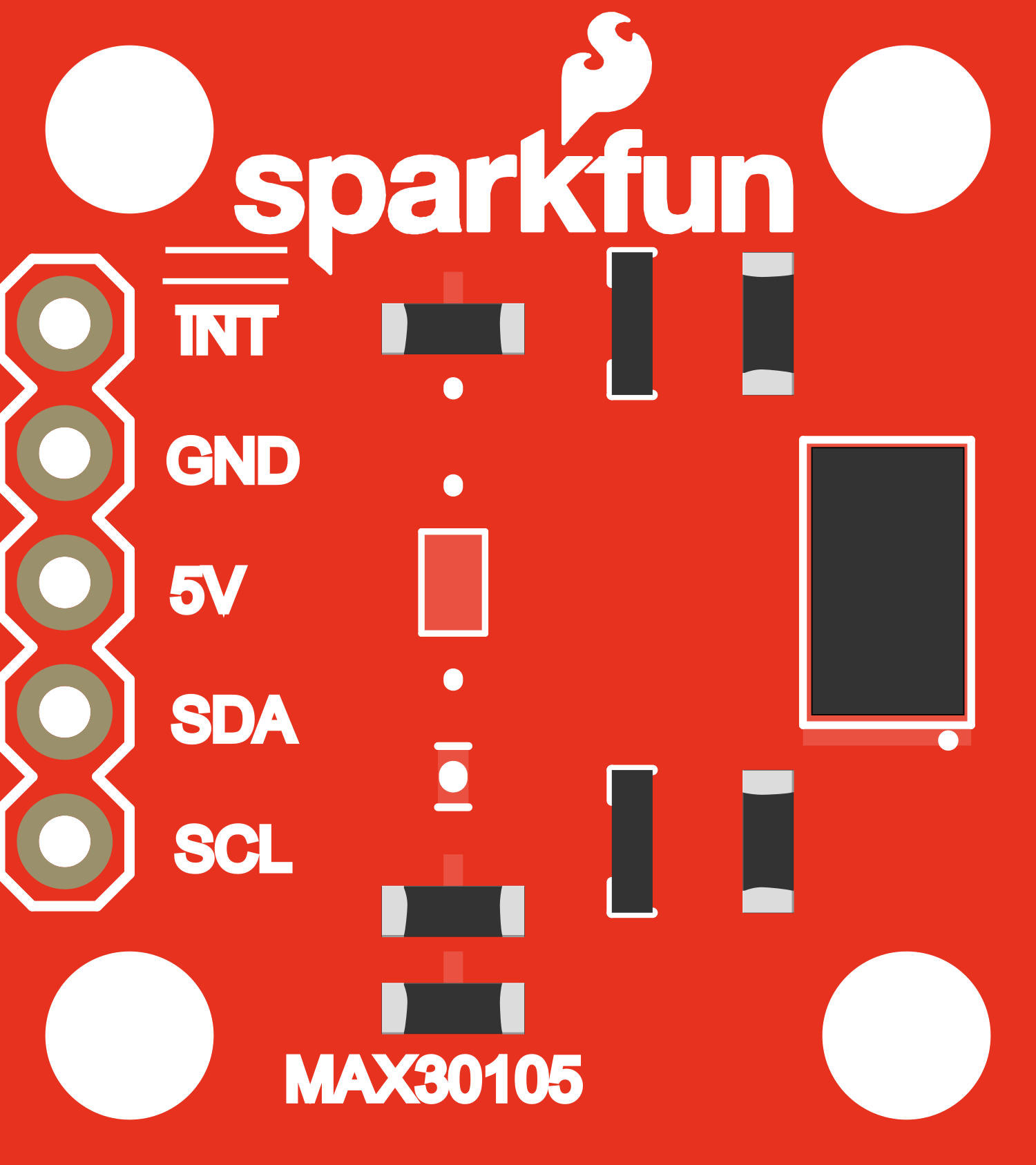
The SparkFun MAX30105 Breakout is a sophisticated sensor module designed for non-invasive optical heart rate monitoring and pulse oximetry. It features the MAX30105 sensor from Maxim Integrated, which is capable of detecting the amount of oxygen in the blood, the volume of blood changes in the body, and even the heart rate through the process of photoplethysmography (PPG). This breakout board simplifies the use of the MAX30105 sensor by providing an easy-to-use I2C interface and onboard LEDs for indication, making it an ideal choice for wearable devices, fitness assistant devices, and medical monitoring applications.
Explore Projects Built with SparkFun MAX30105_Breakout


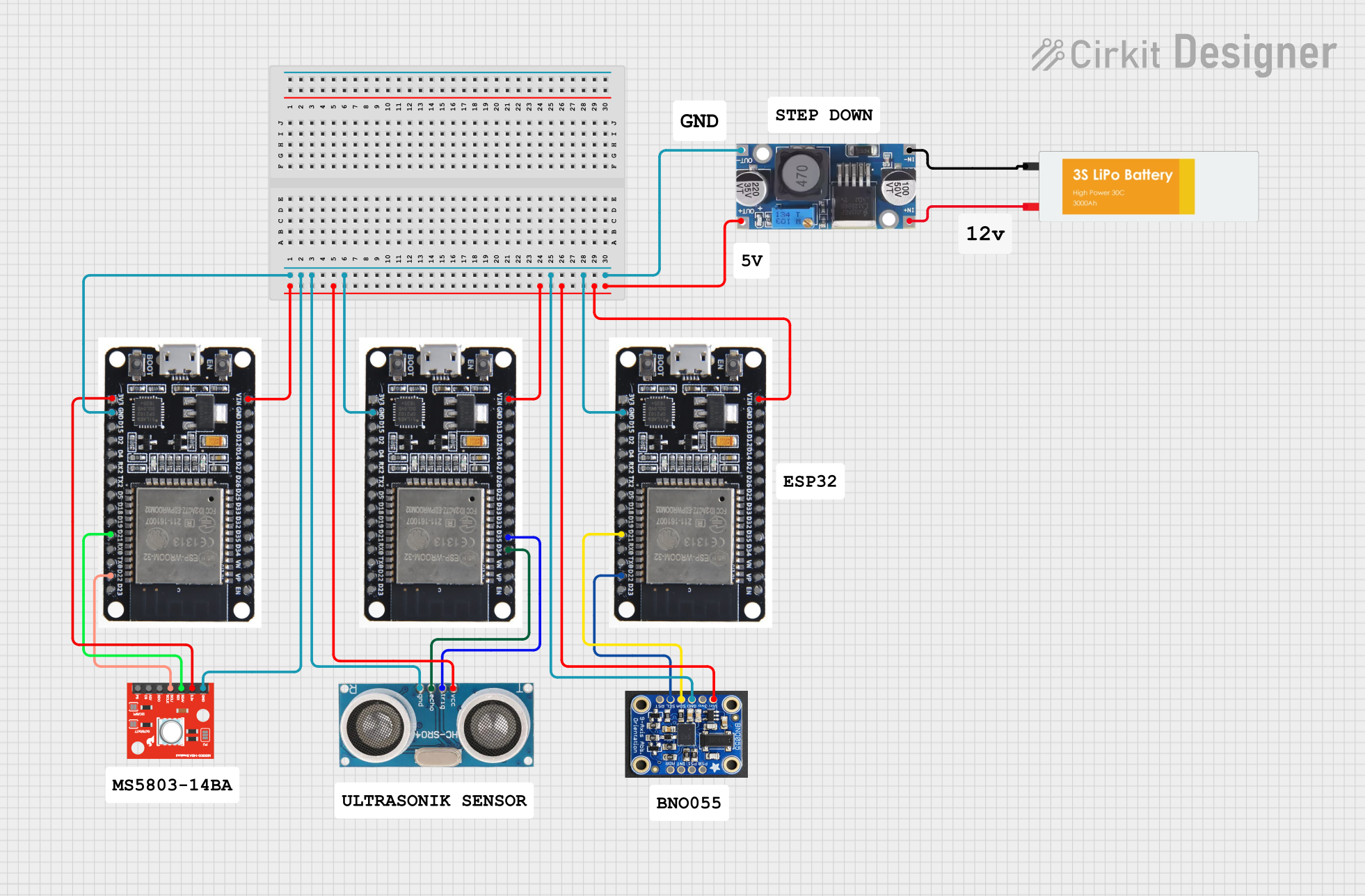
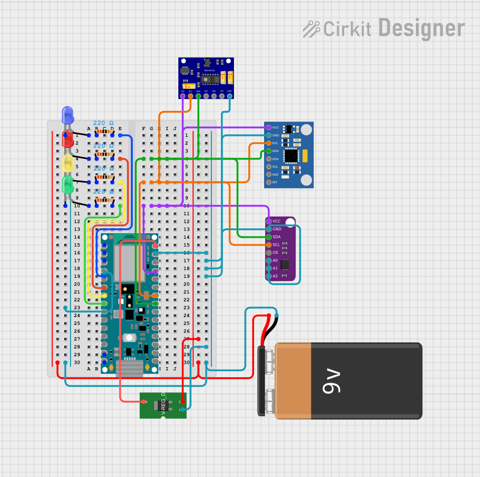
Explore Projects Built with SparkFun MAX30105_Breakout
Technical Specifications
Key Technical Details
- Operating Voltage: 1.8V-3.3V
- Current Consumption: 4mA (typical)
- Operating Temperature: -40°C to +85°C
- LED Wavelengths: 660nm (Red), 880/905nm (IR)
- Sampling Rate: Up to 3200 samples per second
- Communication: I2C interface
Pin Configuration and Descriptions
| Pin Number | Name | Description |
|---|---|---|
| 1 | VIN | Power supply (1.8V-3.3V) |
| 2 | GND | Ground connection |
| 3 | SCL | I2C clock line |
| 4 | SDA | I2C data line |
| 5 | INT | Interrupt pin |
| 6 | RD | Red LED control (optional) |
| 7 | IR | IR LED control (optional) |
| 8 | G | Green LED control (optional) |
Usage Instructions
Integration with a Circuit
- Powering the Sensor: Connect the VIN pin to a 1.8V-3.3V power source and the GND pin to the ground.
- I2C Communication: Connect the SCL and SDA pins to the I2C clock and data lines on your microcontroller.
- Interrupts (Optional): The INT pin can be connected to an interrupt-capable GPIO pin on your microcontroller to handle events like a new data ready.
- LED Control (Optional): The RD, IR, and G pins can be used to control the onboard LEDs if additional functionality is required.
Best Practices
- Ensure that the power supply is stable and within the specified voltage range.
- Use pull-up resistors on the I2C lines if they are not already present on your microcontroller board.
- Avoid placing the sensor under direct sunlight or strong artificial light sources to prevent inaccurate readings.
- Keep the sensor close to the skin for heart rate and SpO2 measurements.
Example Code for Arduino UNO
#include <Wire.h>
#include "MAX30105.h" // Include the MAX30105 library

MAX30105 particleSensor;

void setup() {
  Serial.begin(115200);
  Wire.begin();

  if (!particleSensor.begin(Wire, I2C_SPEED_FAST)) { // Initialize sensor
    Serial.println("MAX30105 was not found. Please check wiring/power.");
    while (1);
  }

  particleSensor.setup(); // Configure sensor with default settings
  particleSensor.setPulseAmplitudeRed(0x0A); // Set Red LED amplitude
  particleSensor.setPulseAmplitudeGreen(0x0A); // Set Green LED amplitude
}

void loop() {
  long irValue = particleSensor.getIR(); // Read IR value
  if (irValue > 50000) { // Check if the sensor is covered
    // Read the heart rate and SpO2 after a finger is placed on the sensor
    float heartRate, spO2;
    if (particleSensor.checkForBeat(irValue) == true) {
      // We sensed a beat!
      long delta = millis() - lastBeat;
      lastBeat = millis();

      heartRate = particleSensor.getRate();
      spO2 = particleSensor.getSpO2();

      Serial.print("Heart rate: ");
      Serial.print(heartRate);
      Serial.print(" bpm. SpO2: ");
      Serial.print(spO2);
      Serial.println("%");
    }
  } else {
    Serial.println("No finger?");
  }
  delay(1000);
}
Troubleshooting and FAQs
Common Issues
- Sensor Not Detected: Ensure that the wiring is correct and the power supply is within the specified range. Check for proper soldering on the breakout board.
- Inaccurate Readings: Make sure the sensor is properly placed on the finger and not exposed to external light sources. Adjust the LED pulse amplitude if necessary.
- No Data on Serial Monitor: Confirm that the correct baud rate is set in the serial monitor and that the board is properly connected to the computer.
FAQs
Q: Can the MAX30105 be used to measure blood pressure? A: No, the MAX30105 is designed for heart rate and SpO2 measurements, not blood pressure.
Q: How can I improve the accuracy of the sensor? A: Ensure a snug fit against the skin, minimize motion, and avoid direct exposure to external light sources.
Q: Is the MAX30105 suitable for medical use? A: The MAX30105 is not FDA-approved for medical use and should not be used for diagnosis or treatment of any conditions.
For further assistance, consult the MAX30105 datasheet and the SparkFun MAX30105 Breakout board schematic available on the SparkFun website.