
How to Use GainSpan WiFi Breakout: Examples, Pinouts, and Specs
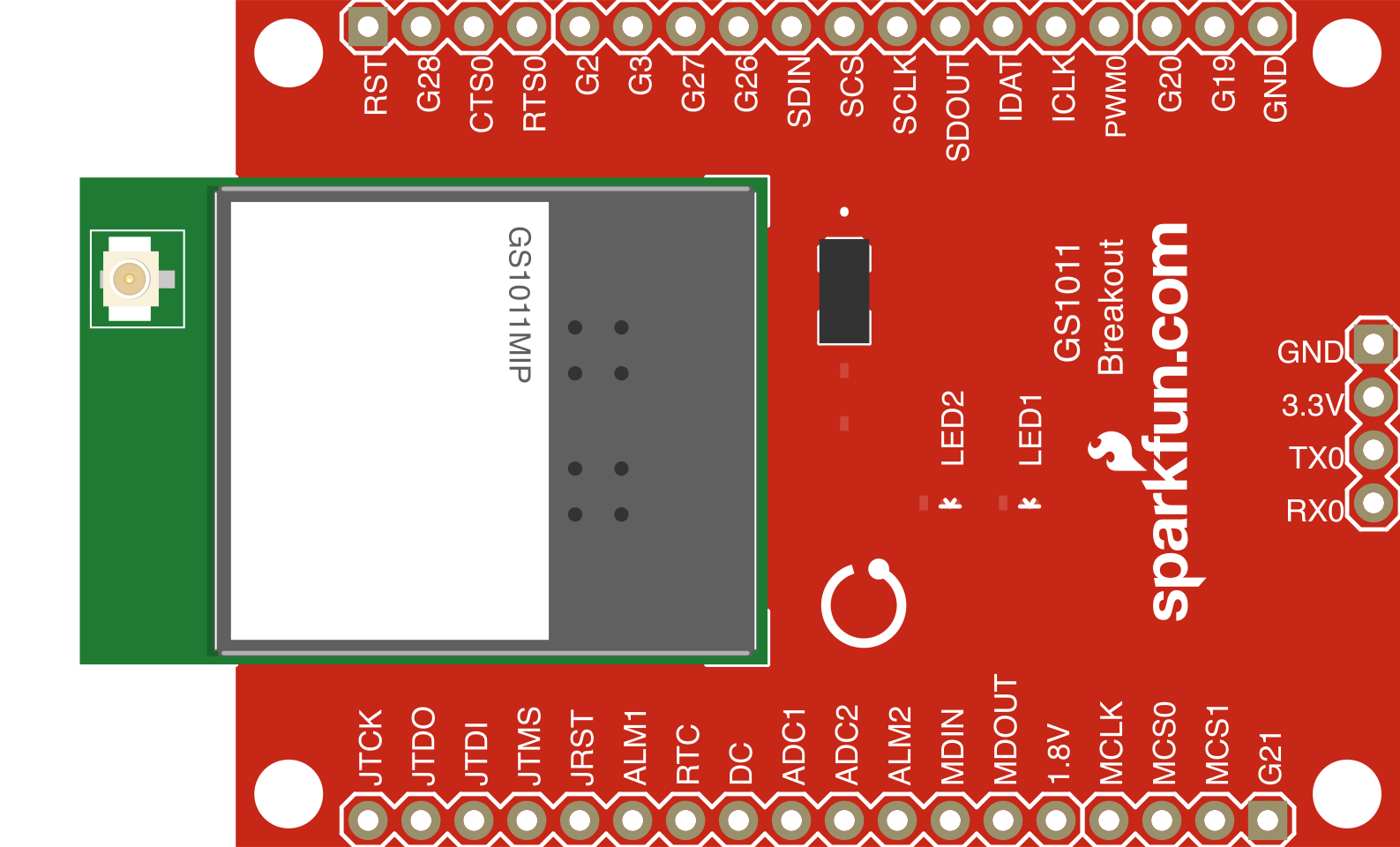
 Design with GainSpan WiFi Breakout in Cirkit Designer
Introduction
The GainSpan WiFi Breakout (Manufacturer Part ID: 10505) by SparkFun Electronics is a compact module designed to provide WiFi connectivity for embedded systems. This breakout board enables devices to connect to wireless networks and communicate over the internet, making it an ideal solution for IoT (Internet of Things) applications. It simplifies the integration of WiFi functionality into projects, offering a reliable and efficient way to connect devices wirelessly.
Explore Projects Built with GainSpan WiFi Breakout
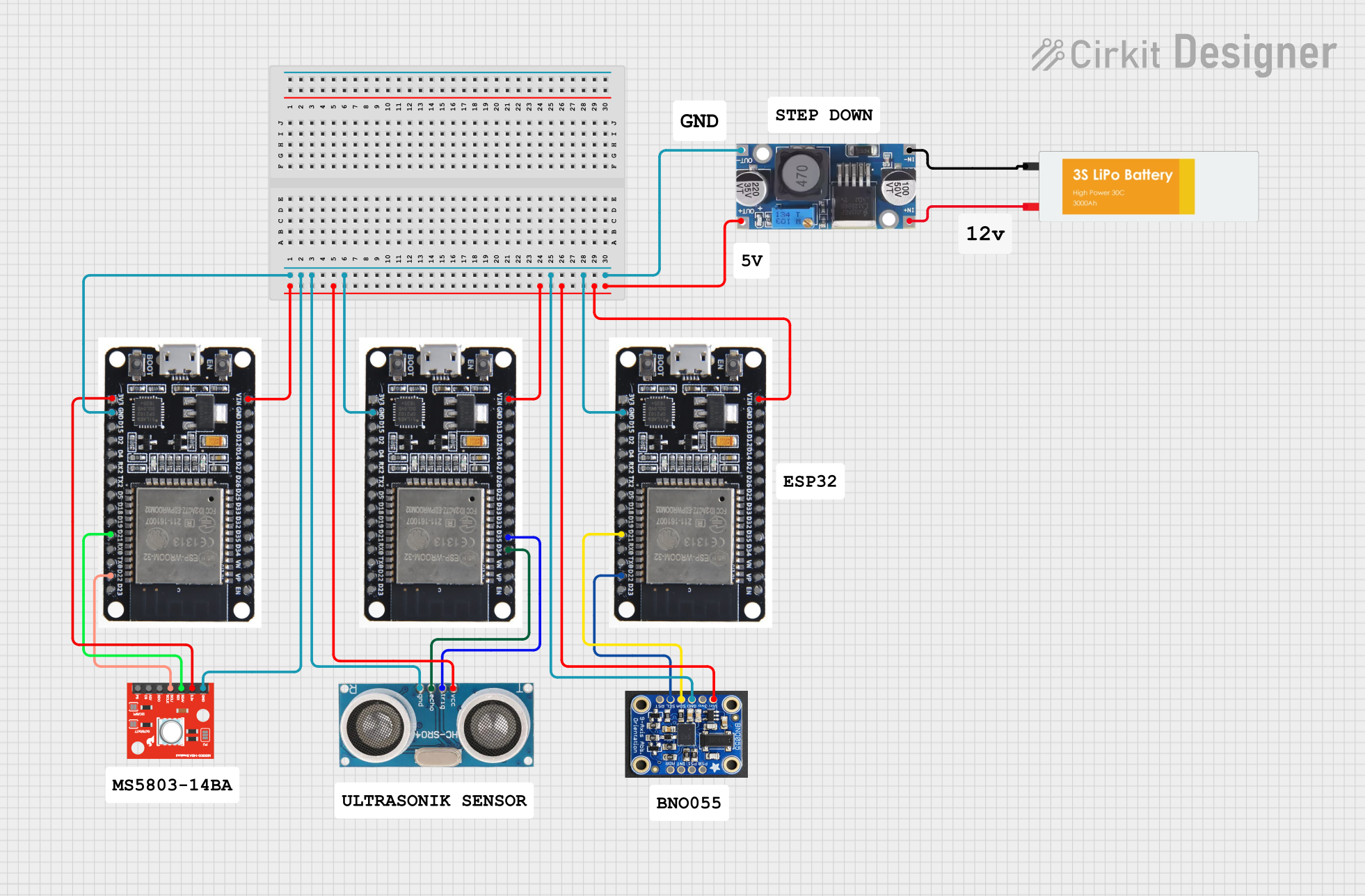 Open Project in Cirkit Designer
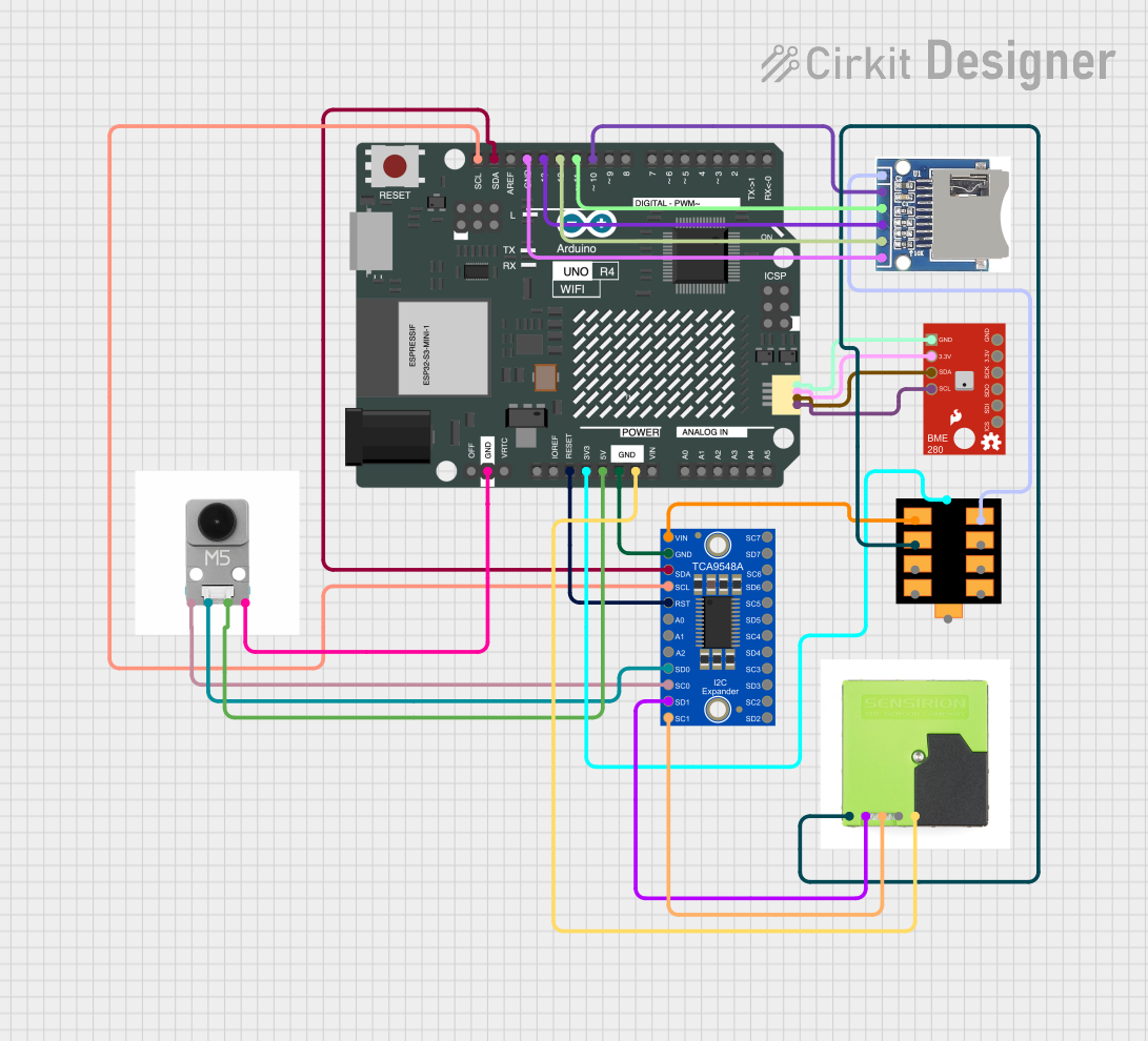 Open Project in Cirkit Designer
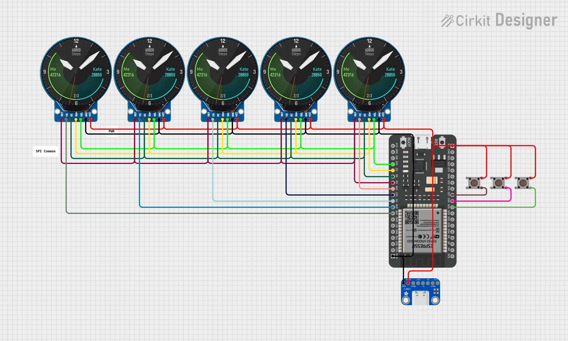 Open Project in Cirkit Designer
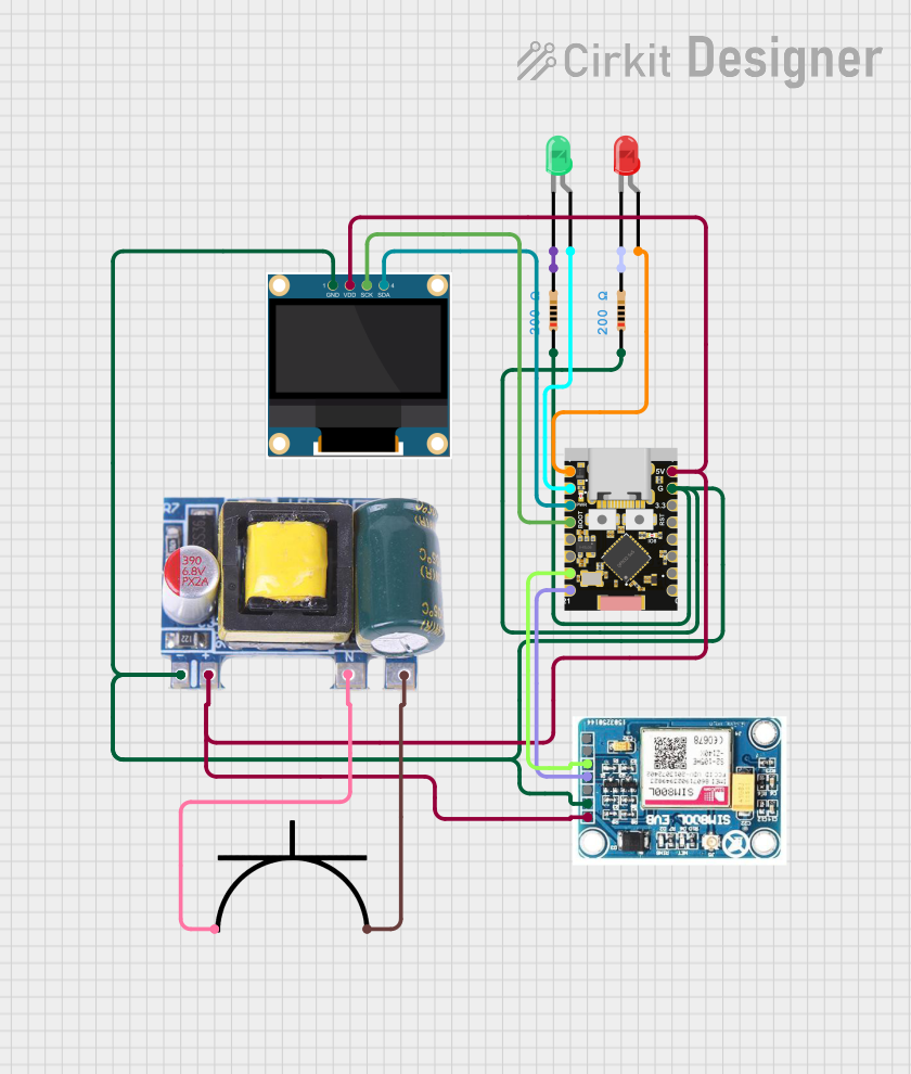 Open Project in Cirkit Designer
Explore Projects Built with GainSpan WiFi Breakout
Open Project in Cirkit DesignerOpen Project in Cirkit DesignerOpen Project in Cirkit DesignerOpen Project in Cirkit DesignerCommon Applications and Use Cases
- IoT Devices: Smart home systems, environmental monitoring, and industrial IoT.
- Wireless Data Logging: Collecting and transmitting sensor data to cloud platforms.
- Remote Control Systems: Enabling wireless control of robots, drones, or appliances.
- Prototyping: Rapid development of WiFi-enabled projects for hobbyists and engineers.
Technical Specifications
The GainSpan WiFi Breakout is built to provide robust wireless connectivity with the following key specifications:
| Specification | Details |
|---|---|
| Manufacturer | SparkFun Electronics |
| Part ID | 10505 |
| Wireless Standard | IEEE 802.11b/g/n |
| Operating Voltage | 3.3V (logic level) |
| Power Supply Voltage | 3.3V to 5V |
| Current Consumption | 200mA (typical during transmission) |
| Data Rate | Up to 72.2 Mbps |
| Security Protocols | WEP, WPA/WPA2-PSK |
| Communication Interface | UART (default), SPI |
| Dimensions | 1.0" x 1.0" (25.4mm x 25.4mm) |
| Operating Temperature | -40°C to +85°C |
Pin Configuration and Descriptions
The GainSpan WiFi Breakout features a simple pinout for easy integration into your projects. Below is the pin configuration:
| Pin | Name | Description |
|---|---|---|
| 1 | GND | Ground connection |
| 2 | VCC | Power supply input (3.3V to 5V) |
| 3 | TX | UART Transmit pin (3.3V logic level) |
| 4 | RX | UART Receive pin (3.3V logic level) |
| 5 | GPIO0 | General-purpose I/O pin (used for configuration or control) |
| 6 | GPIO1 | General-purpose I/O pin |
| 7 | RESET | Active-low reset pin |
| 8 | SPI_CS | SPI Chip Select (used in SPI communication mode) |
| 9 | SPI_CLK | SPI Clock (used in SPI communication mode) |
| 10 | SPI_MOSI | SPI Master Out Slave In (used in SPI communication mode) |
| 11 | SPI_MISO | SPI Master In Slave Out (used in SPI communication mode) |
Usage Instructions
How to Use the Component in a Circuit
- Power Supply: Connect the
VCCpin to a 3.3V or 5V power source and theGNDpin to ground. - Communication Interface:
- For UART communication, connect the
TXandRXpins to the corresponding UART pins on your microcontroller. - For SPI communication, connect the
SPI_CS,SPI_CLK,SPI_MOSI, andSPI_MISOpins to the SPI interface of your microcontroller.
- For UART communication, connect the
- Reset: Optionally, connect the
RESETpin to a GPIO pin on your microcontroller to allow software-controlled resets. - GPIO Pins: Use
GPIO0andGPIO1for additional control or configuration as needed.
Important Considerations and Best Practices
- Voltage Levels: Ensure that the logic levels of your microcontroller match the 3.3V logic level of the GainSpan WiFi Breakout. Use a level shifter if necessary.
- Antenna Placement: Avoid placing the module near metal objects or other components that may interfere with the WiFi signal.
- Power Supply: Provide a stable power supply to avoid communication issues or unexpected resets.
- Firmware Updates: Check for firmware updates from SparkFun to ensure optimal performance and compatibility.
Example: Connecting to an Arduino UNO
Below is an example of how to connect the GainSpan WiFi Breakout to an Arduino UNO and send data over WiFi.
Wiring Diagram
| GainSpan Pin | Arduino Pin |
|---|---|
| VCC | 3.3V |
| GND | GND |
| TX | RX (Pin 0) |
| RX | TX (Pin 1) |
| RESET | Digital Pin 7 |
Arduino Code Example
#include <SoftwareSerial.h>

// Define RX and TX pins for SoftwareSerial
SoftwareSerial wifiSerial(2, 3); // RX = Pin 2, TX = Pin 3

void setup() {
  // Start serial communication with the WiFi module
  wifiSerial.begin(9600);
  Serial.begin(9600); // For debugging with the Serial Monitor

  // Send initialization commands to the WiFi module
  wifiSerial.println("AT"); // Test communication
  delay(1000);

  // Connect to a WiFi network
  wifiSerial.println("AT+CWJAP=\"YourSSID\",\"YourPassword\"");
  delay(5000);

  // Check connection status
  wifiSerial.println("AT+CIFSR"); // Get IP address
}

void loop() {
  // Send data to a server (example)
  wifiSerial.println("AT+CIPSTART=\"TCP\",\"example.com\",80");
  delay(2000);

  wifiSerial.println("AT+CIPSEND=18"); // Send 18 bytes of data
  delay(1000);

  wifiSerial.println("GET / HTTP/1.1");
  wifiSerial.println("Host: example.com");
  wifiSerial.println();
  delay(5000);

  // Read and print the response
  while (wifiSerial.available()) {
    Serial.write(wifiSerial.read());
  }
}
Troubleshooting and FAQs
Common Issues and Solutions
No Response from the Module
- Cause: Incorrect wiring or baud rate mismatch.
- Solution: Double-check the wiring and ensure the baud rate matches the module's default (9600 bps).
WiFi Connection Fails
- Cause: Incorrect SSID or password.
- Solution: Verify the SSID and password. Ensure the WiFi network is within range.
Unstable Communication
- Cause: Insufficient power supply or interference.
- Solution: Use a stable power source and avoid placing the module near sources of interference.
Module Does Not Reset
- Cause: RESET pin not properly connected.
- Solution: Ensure the RESET pin is connected to a GPIO pin or manually pull it low to reset.
FAQs
Can I use the module with 5V logic microcontrollers?
- Yes, but you must use a level shifter to convert 5V signals to 3.3V.
What is the maximum range of the WiFi module?
- The range depends on the environment but typically extends up to 100 meters in open spaces.
Does the module support HTTPS?
- No, the module supports HTTP but does not natively support HTTPS.
Can I update the firmware?
- Yes, firmware updates can be performed via the UART interface. Refer to SparkFun's documentation for detailed instructions.