
How to Use wz3605e: Examples, Pinouts, and Specs
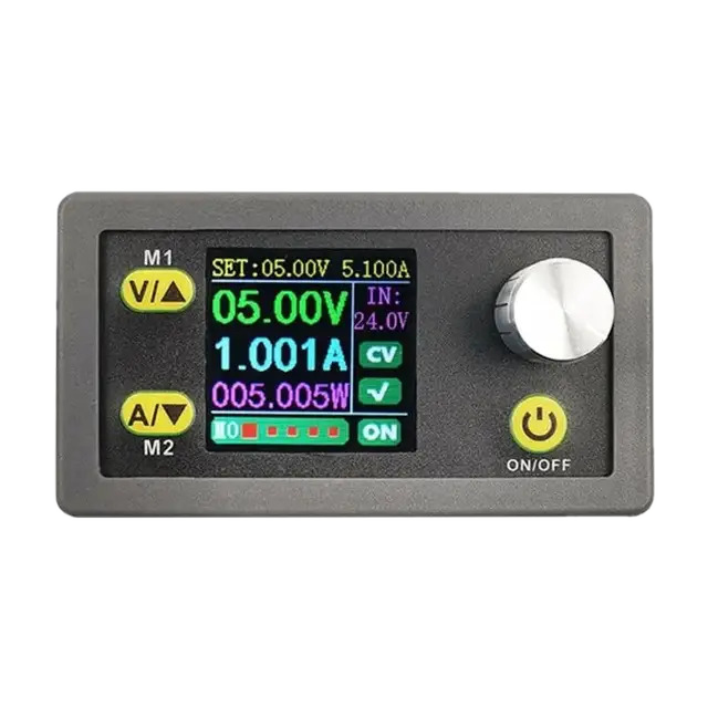
 Design with wz3605e in Cirkit Designer
Introduction
The WZ3605E, manufactured by Stas (Part ID: 5), is a high-performance voltage regulator designed to deliver a stable output voltage with low dropout. This component is ideal for power management applications, ensuring consistent voltage levels for sensitive electronic components. Its compact design and reliable performance make it a popular choice in consumer electronics, industrial systems, and embedded devices.
Explore Projects Built with wz3605e
 Open Project in Cirkit Designer
 Open Project in Cirkit Designer
 Open Project in Cirkit Designer
 Open Project in Cirkit Designer
Explore Projects Built with wz3605e
Open Project in Cirkit DesignerOpen Project in Cirkit DesignerOpen Project in Cirkit DesignerOpen Project in Cirkit DesignerCommon Applications
- Power supply stabilization for microcontrollers and sensors
- Battery-powered devices requiring low dropout voltage
- Consumer electronics such as smartphones and tablets
- Industrial automation systems
- Embedded systems and IoT devices
Technical Specifications
Key Specifications
| Parameter | Value |
|---|---|
| Input Voltage Range | 2.5V to 18V |
| Output Voltage Range | 1.2V to 5.0V (fixed options) |
| Maximum Output Current | 500mA |
| Dropout Voltage | 0.2V (typical at 500mA load) |
| Quiescent Current | 50µA (typical) |
| Operating Temperature | -40°C to +125°C |
| Package Type | SOT-23-5 |
Pin Configuration
The WZ3605E is available in a 5-pin SOT-23 package. The pinout is as follows:
| Pin Number | Pin Name | Description |
|---|---|---|
| 1 | VIN | Input voltage pin (connect to power source) |
| 2 | GND | Ground pin (connect to circuit ground) |
| 3 | EN | Enable pin (active high, enables the regulator) |
| 4 | VOUT | Regulated output voltage pin |
| 5 | NC | No connection (leave unconnected or grounded) |
Usage Instructions
How to Use the WZ3605E in a Circuit
- Input Capacitor: Connect a ceramic capacitor (e.g., 1µF) between the VIN pin and GND to stabilize the input voltage.
- Output Capacitor: Connect a ceramic capacitor (e.g., 1µF to 10µF) between the VOUT pin and GND to ensure stable output voltage.
- Enable Pin: The EN pin must be pulled high (above 1.2V) to enable the regulator. If unused, connect it to VIN.
- Load Connection: Connect the load to the VOUT pin. Ensure the load does not exceed the maximum output current of 500mA.
- Thermal Considerations: Ensure adequate heat dissipation, especially in high-current applications.
Example Circuit
Below is a basic circuit diagram for using the WZ3605E:
   VIN (2.5V-18V) ----+----[C1: 1µF]----+---- VIN (Pin 1)
                      |                 |
                     GND               GND (Pin 2)
                      |
                     EN (Pin 3) ----+----[Pull-up Resistor]---- VIN
                                    |
                                   GND
                      |
                     VOUT (Pin 4) ----+----[C2: 10µF]----+---- Load
                                      |                  |
                                     GND                GND
Arduino UNO Example Code
The WZ3605E can be used to power an Arduino UNO or other microcontrollers. Below is an example code snippet to toggle the EN pin using a digital output pin from the Arduino:
// Define the pin connected to the EN pin of the WZ3605E
const int enablePin = 7;

void setup() {
  // Set the enable pin as an output
  pinMode(enablePin, OUTPUT);

  // Enable the voltage regulator
  digitalWrite(enablePin, HIGH); // Pull EN pin high to enable the regulator
}

void loop() {
  // The regulator remains enabled; add your application code here
  delay(1000); // Placeholder for main loop functionality
}
Important Considerations
- Ensure the input voltage is within the specified range (2.5V to 18V).
- Use low-ESR ceramic capacitors for input and output to maintain stability.
- Avoid exceeding the maximum output current of 500mA to prevent damage.
- If the EN pin is not used, connect it to VIN to keep the regulator enabled.
Troubleshooting and FAQs
Common Issues and Solutions
| Issue | Possible Cause | Solution |
|---|---|---|
| No output voltage | EN pin not pulled high | Ensure the EN pin is connected to VIN or a high signal. |
| Output voltage is unstable | Insufficient output capacitor | Use a low-ESR ceramic capacitor (1µF to 10µF) on VOUT. |
| Regulator overheating | Excessive load current | Reduce the load current to below 500mA. |
| High input voltage ripple | Insufficient input capacitor | Add a ceramic capacitor (1µF or higher) on VIN. |
| Noisy output voltage | Poor PCB layout or grounding issues | Ensure proper grounding and minimize trace lengths. |
FAQs
Can the WZ3605E be used with a 3.3V microcontroller? Yes, the WZ3605E can regulate input voltages down to 3.3V, provided the dropout voltage is accounted for.
What happens if the EN pin is left floating? The regulator may not function correctly. Always connect the EN pin to VIN or a high signal to enable the regulator.
Can I use electrolytic capacitors instead of ceramic capacitors? While possible, ceramic capacitors are recommended due to their low ESR, which ensures stability.
Is the WZ3605E protected against short circuits? Yes, the WZ3605E includes built-in short-circuit protection to safeguard the device and connected components.
By following this documentation, users can effectively integrate the WZ3605E into their designs and troubleshoot common issues with ease.