How to Use 3.5mm 3-Pin TRS: Examples, Pinouts, and Specs

Introduction
The 3.5mm 3-Pin TRS (Tip-Ring-Sleeve) connector is a widely used audio connector designed for transmitting stereo audio signals. It is commonly found in headphones, audio cables, portable audio devices, and various consumer electronics. The connector features three distinct contact points: the tip, which carries the left audio channel; the ring, which carries the right audio channel; and the sleeve, which serves as the ground connection.
Explore Projects Built with 3.5mm 3-Pin TRS
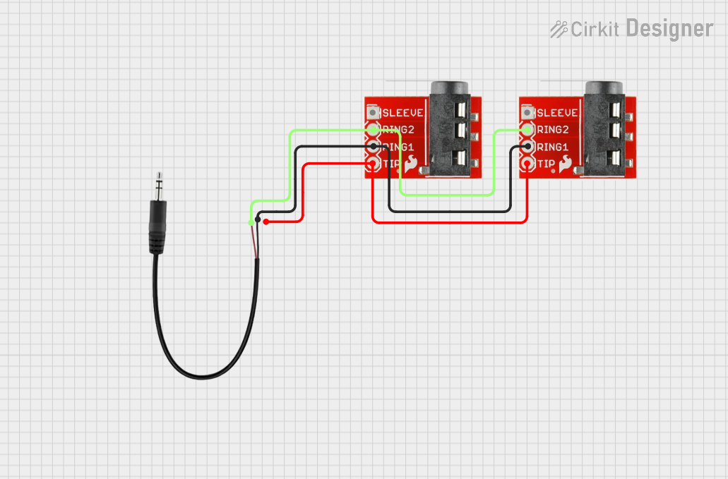

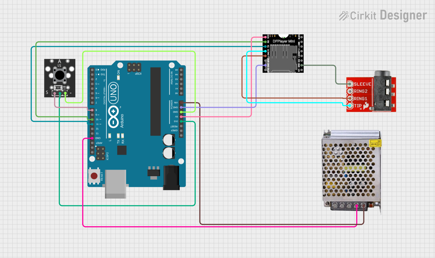
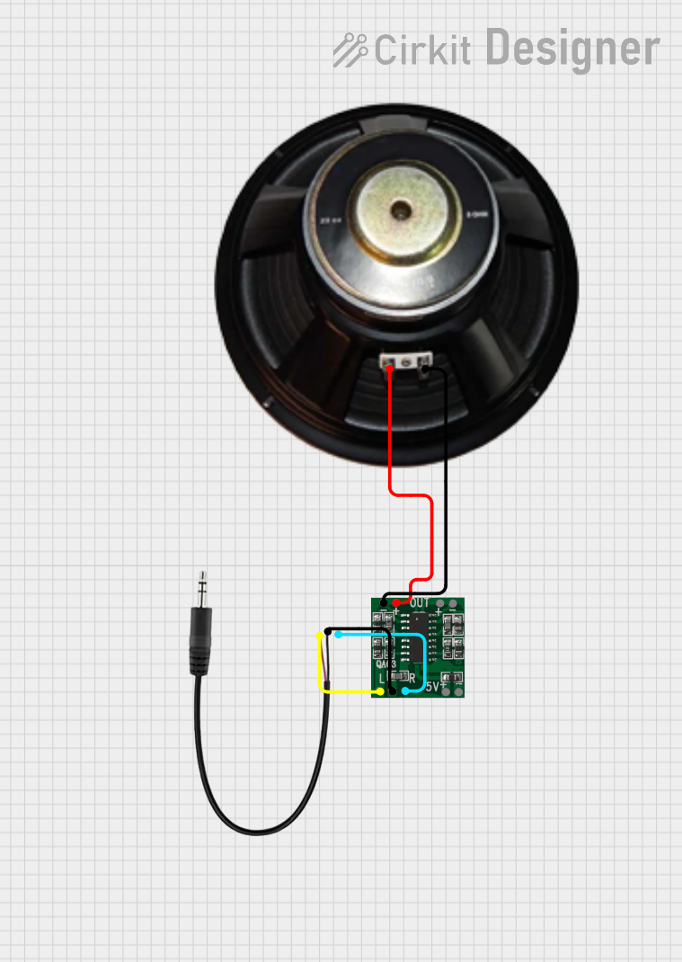
Explore Projects Built with 3.5mm 3-Pin TRS
Common Applications and Use Cases
- Headphones and Earphones: Used to connect audio devices to headphones for stereo sound.
- Audio Cables: Facilitates stereo audio transmission between devices like smartphones, laptops, and speakers.
- Microphones: Some microphones use TRS connectors for audio output.
- Portable Audio Devices: Found in MP3 players, smartphones, and tablets for audio output.
- DIY Electronics Projects: Used in custom audio circuits and projects requiring stereo audio connections.
Technical Specifications
Key Technical Details
- Connector Type: 3.5mm TRS (Tip-Ring-Sleeve)
- Number of Contacts: 3 (Tip, Ring, Sleeve)
- Signal Type: Stereo audio
- Material: Typically nickel-plated or gold-plated for improved conductivity and corrosion resistance
- Maximum Voltage: Typically up to 12V (varies by application)
- Maximum Current: Typically up to 1A (varies by application)
- Impedance: Low impedance for audio signal transmission
- Durability: Rated for thousands of insertion/removal cycles
Pin Configuration and Descriptions
The 3.5mm 3-Pin TRS connector has three distinct contact points, as detailed in the table below:
| Pin Name | Contact Position | Function | Description |
|---|---|---|---|
| Tip (T) | End of the plug | Left Audio Channel | Carries the left channel audio signal. |
| Ring (R) | Middle contact | Right Audio Channel | Carries the right channel audio signal. |
| Sleeve (S) | Base of the plug | Ground | Serves as the ground connection. |
Usage Instructions
How to Use the Component in a Circuit
- Identify the Pins: Locate the tip, ring, and sleeve on the connector. The tip is at the end, the ring is the middle contact, and the sleeve is the base.
- Connect to Audio Source:
- Solder or connect the tip to the left audio channel output.
- Solder or connect the ring to the right audio channel output.
- Solder or connect the sleeve to the ground of the audio source.
- Ensure Proper Polarity: Verify that the left and right channels are correctly connected to avoid channel inversion.
- Test the Connection: Plug the TRS connector into the corresponding jack and test the audio output for clarity and stereo separation.
Important Considerations and Best Practices
- Avoid Short Circuits: Ensure that the solder joints for the tip, ring, and sleeve do not touch each other to prevent short circuits.
- Use Heat Shrink Tubing: Apply heat shrink tubing over soldered connections to provide insulation and strain relief.
- Check Compatibility: Ensure the device you are connecting to supports a 3.5mm TRS connector and stereo audio.
- Gold-Plated Connectors: For better conductivity and reduced corrosion, consider using gold-plated TRS connectors.
- Cable Shielding: Use shielded cables to minimize noise and interference in audio signals.
Example: Connecting to an Arduino UNO
While the 3.5mm TRS connector is not directly compatible with Arduino for audio signal processing, it can be used in conjunction with an audio amplifier or analog input. Below is an example of reading an audio signal from the TRS connector using an Arduino UNO:
// Example: Reading audio signal from a 3.5mm TRS connector
// Connect the tip (left channel) to Arduino analog pin A0
// Connect the sleeve (ground) to Arduino GND
// Note: This example assumes a low-voltage audio signal

const int audioPin = A0; // Analog pin connected to the tip (left channel)

void setup() {
  Serial.begin(9600); // Initialize serial communication
}

void loop() {
  int audioSignal = analogRead(audioPin); // Read the audio signal
  Serial.println(audioSignal); // Print the signal value to the Serial Monitor
  delay(10); // Small delay for stability
}
Note: Audio signals may need to be attenuated or conditioned before connecting to the Arduino to avoid damaging the microcontroller.
Troubleshooting and FAQs
Common Issues Users Might Face
No Audio Output:
- Cause: Incorrect wiring or loose connections.
- Solution: Verify that the tip, ring, and sleeve are correctly connected to the audio source and destination.
Mono Audio Instead of Stereo:
- Cause: One of the audio channels (tip or ring) is not connected.
- Solution: Check the connections for both the tip and ring to ensure proper stereo output.
Static or Noise in Audio:
- Cause: Poor cable shielding or loose connections.
- Solution: Use shielded cables and ensure all connections are secure.
Connector Does Not Fit:
- Cause: Using the wrong connector size (e.g., 2.5mm or 6.35mm instead of 3.5mm).
- Solution: Confirm that the device requires a 3.5mm TRS connector.
Solutions and Tips for Troubleshooting
- Inspect the Connector: Check for physical damage, such as bent pins or worn-out plating.
- Test with Another Device: Plug the TRS connector into a different device to rule out issues with the original device.
- Use a Multimeter: Test continuity between the tip, ring, and sleeve to ensure proper connections.
- Clean the Connector: Use isopropyl alcohol and a soft cloth to clean the connector for better contact.
By following this documentation, users can effectively utilize the 3.5mm 3-Pin TRS connector in their audio projects and troubleshoot common issues with ease.