How to Use 5v UPS : Examples, Pinouts, and Specs
Introduction
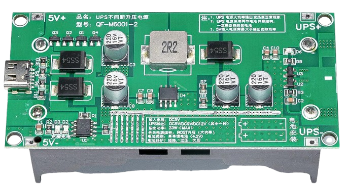
A 5V Uninterruptible Power Supply (UPS) is a compact power management device designed to provide a stable 5V output to electronic devices during power outages or voltage fluctuations. It ensures uninterrupted operation of critical systems, such as microcontrollers, IoT devices, routers, and other low-power electronics. The 5V UPS typically integrates a rechargeable battery, charging circuitry, and voltage regulation to maintain consistent power delivery.
Explore Projects Built with 5v UPS


Explore Projects Built with 5v UPS
Common Applications and Use Cases
- Backup power for Raspberry Pi, Arduino, and other microcontrollers.
- Ensuring uninterrupted operation of IoT devices during power outages.
- Powering small routers, modems, or network devices.
- Providing stable power to sensors and data loggers in remote locations.
- Preventing data loss or corruption in embedded systems.
Technical Specifications
The following table outlines the key technical details of a typical 5V UPS:
| Parameter | Specification |
|---|---|
| Input Voltage | 5V DC |
| Output Voltage | 5V DC (regulated) |
| Output Current | Up to 2A (varies by model) |
| Battery Type | Lithium-ion or Lithium-polymer |
| Battery Capacity | 1000mAh to 5000mAh (varies by model) |
| Charging Current | 500mA to 1A |
| Protection Features | Overcharge, over-discharge, short-circuit |
| Dimensions | Varies by model (e.g., 60mm x 40mm x 20mm) |
| Operating Temperature | 0°C to 50°C |
Pin Configuration and Descriptions
The 5V UPS typically has the following pin configuration:
| Pin Name | Description |
|---|---|
| VIN | Input voltage pin (5V DC) for charging the UPS battery. |
| GND | Ground connection for both input and output. |
| VOUT | Regulated 5V output pin to power connected devices. |
| BAT+ | Positive terminal of the internal battery (not typically user-accessible). |
| BAT- | Negative terminal of the internal battery (not typically user-accessible). |
| CHG LED | LED indicator for charging status (e.g., ON when charging, OFF when charged). |
| PWR LED | LED indicator for power output status (e.g., ON when output is active). |
Usage Instructions
How to Use the 5V UPS in a Circuit
Connect the Input Power Source:
- Connect a 5V DC power source (e.g., USB adapter) to the
VINandGNDpins. - Ensure the input voltage is stable and within the specified range.
- Connect a 5V DC power source (e.g., USB adapter) to the
Connect the Load Device:
- Connect the device you want to power to the
VOUTandGNDpins. - Ensure the load does not exceed the maximum output current rating of the UPS.
- Connect the device you want to power to the
Monitor the LEDs:
- The
CHG LEDwill indicate the charging status of the internal battery. - The
PWR LEDwill indicate whether the UPS is supplying power to the load.
- The
Battery Backup Operation:
- During a power outage, the UPS will automatically switch to battery mode, maintaining a stable 5V output.
- When power is restored, the UPS will recharge the battery while continuing to power the load.
Important Considerations and Best Practices
- Battery Capacity: Choose a 5V UPS with sufficient battery capacity to meet the runtime requirements of your application.
- Load Current: Ensure the connected device's current draw does not exceed the UPS's maximum output current.
- Heat Dissipation: Avoid placing the UPS in enclosed spaces without proper ventilation, as heat may build up during operation.
- Battery Maintenance: Periodically check the battery health and replace it if the capacity significantly degrades over time.
- Polarity: Double-check all connections to avoid reverse polarity, which may damage the UPS or connected devices.
Example: Using a 5V UPS with an Arduino UNO
The following example demonstrates how to connect a 5V UPS to an Arduino UNO for uninterrupted operation:
Circuit Connection
- Connect the
VOUTpin of the 5V UPS to the5Vpin of the Arduino UNO. - Connect the
GNDpin of the 5V UPS to theGNDpin of the Arduino UNO. - Connect a 5V DC power source to the
VINandGNDpins of the UPS.
Sample Arduino Code
// Example code to demonstrate uninterrupted operation of an Arduino UNO
// powered by a 5V UPS. The Arduino will blink an LED continuously.

const int ledPin = 13; // Pin connected to the onboard LED

void setup() {
  pinMode(ledPin, OUTPUT); // Set the LED pin as an output
}

void loop() {
  digitalWrite(ledPin, HIGH); // Turn the LED on
  delay(1000);                // Wait for 1 second
  digitalWrite(ledPin, LOW);  // Turn the LED off
  delay(1000);                // Wait for 1 second
}
Troubleshooting and FAQs
Common Issues and Solutions
Issue: The UPS does not power the connected device.
- Solution: Check the input power source and ensure it is providing 5V DC. Verify that the load current does not exceed the UPS's maximum output current.
Issue: The battery does not charge.
- Solution: Ensure the input voltage is stable and within the specified range. Check the
CHG LEDfor charging status. If the battery is old or damaged, consider replacing it.
- Solution: Ensure the input voltage is stable and within the specified range. Check the
Issue: The UPS overheats during operation.
- Solution: Ensure proper ventilation around the UPS. Avoid overloading the UPS by connecting devices that draw more current than its rated capacity.
Issue: The output voltage drops below 5V during battery mode.
- Solution: Verify the battery's charge level. If the battery is nearly depleted, recharge it before use. Ensure the load is within the UPS's capacity.
FAQs
Q: Can I use the 5V UPS to power a Raspberry Pi?
A: Yes, as long as the Raspberry Pi's power requirements (voltage and current) are within the UPS's specifications.Q: How long will the UPS provide backup power?
A: The runtime depends on the battery capacity and the power consumption of the connected device. For example, a 2000mAh battery can power a 500mA load for approximately 4 hours.Q: Can I replace the internal battery?
A: Some models allow battery replacement, but it is recommended to consult the manufacturer's documentation before attempting to replace the battery.Q: Is the UPS safe to use with sensitive electronics?
A: Yes, most 5V UPS devices include protection features such as overcharge, over-discharge, and short-circuit protection to ensure safe operation.