How to Use RELÉ DE SEGURANÇA: Examples, Pinouts, and Specs

 Design with RELÉ DE SEGURANÇA in Cirkit Designer
Introduction
A safety relay (Relé de Segurança) is an electromechanical device designed to monitor safety circuits and ensure the safe operation of machinery. It plays a critical role in industrial automation and safety systems by detecting faults and interrupting power to prevent accidents. Safety relays are commonly used in emergency stop circuits, light curtain systems, and other safety-critical applications.
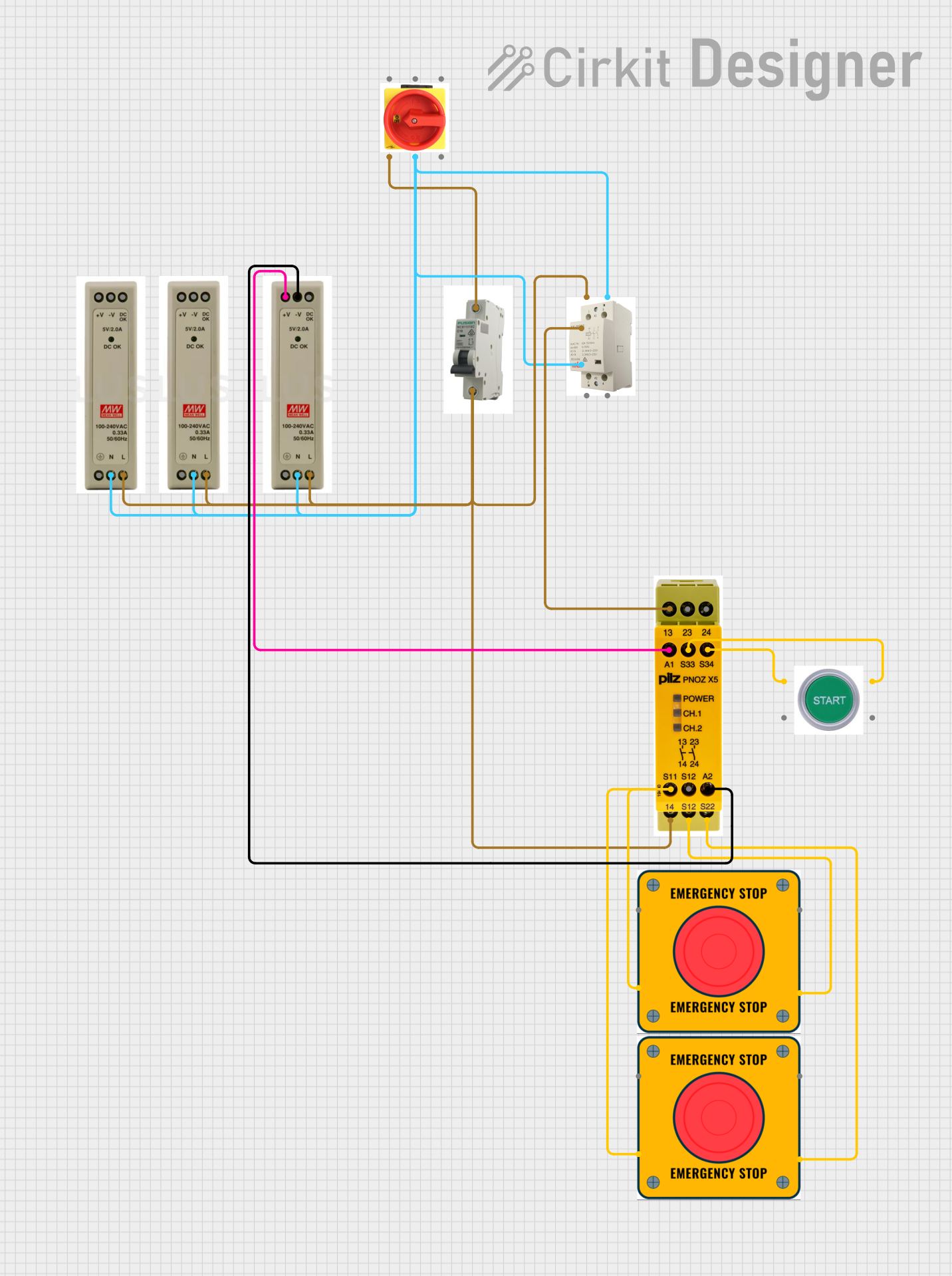
Explore Projects Built with RELÉ DE SEGURANÇA

 Open Project in Cirkit Designer
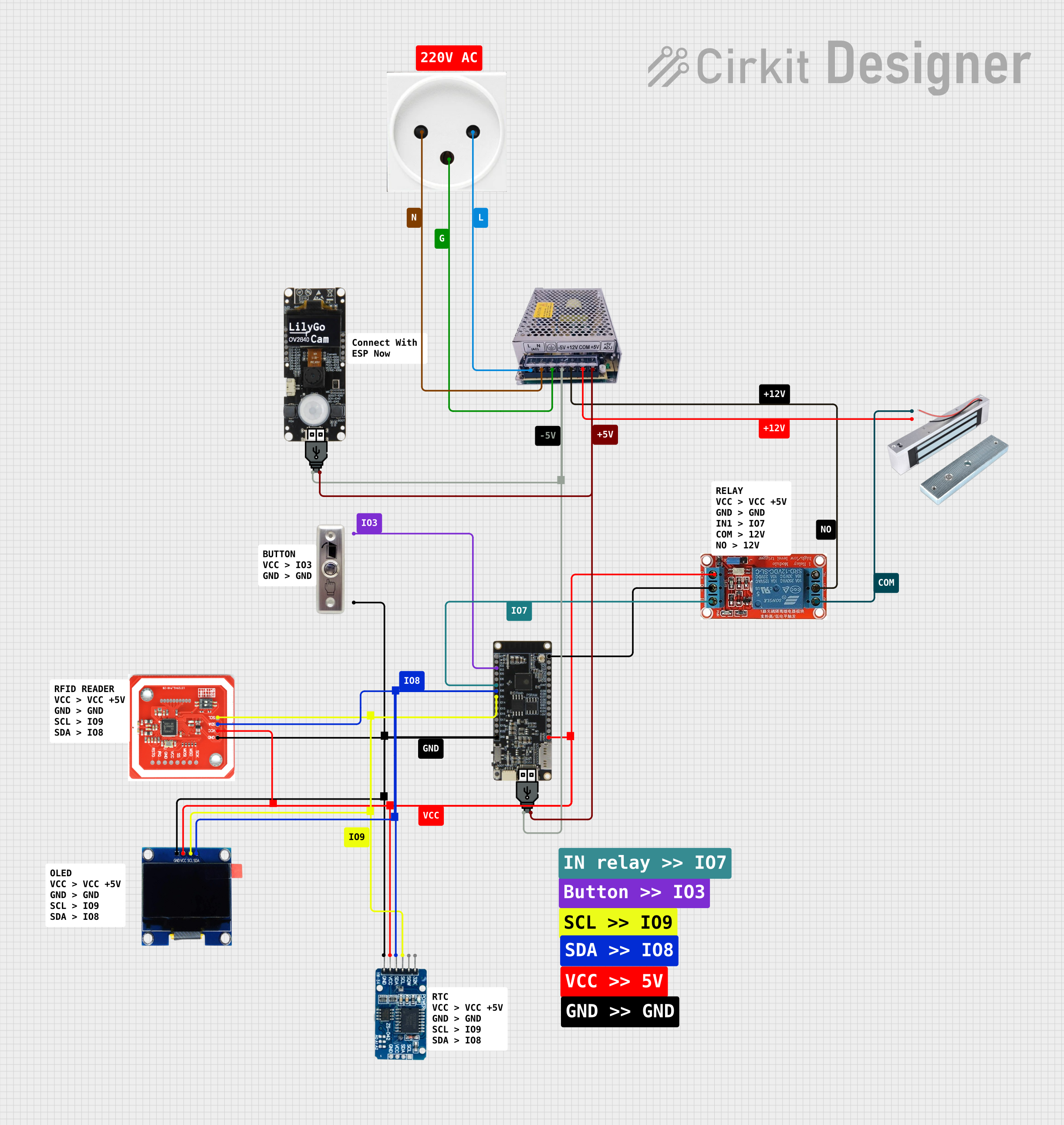
 Open Project in Cirkit Designer
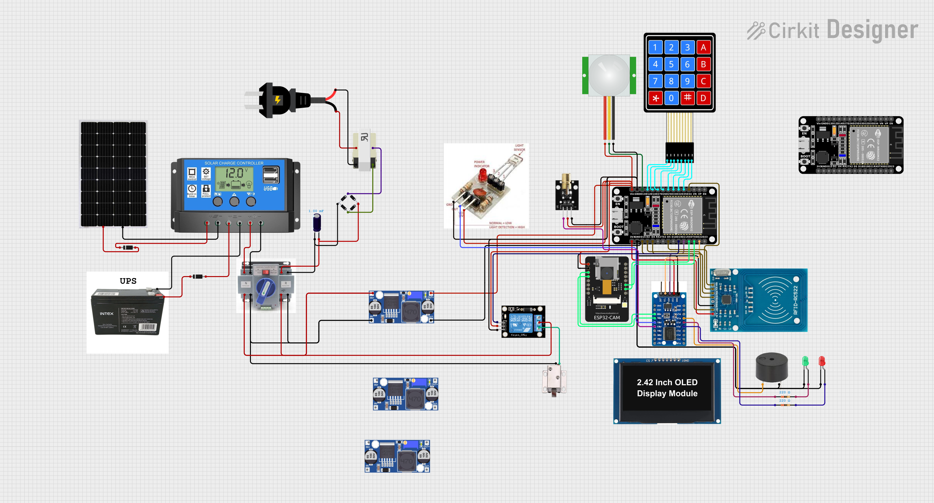
 Open Project in Cirkit Designer
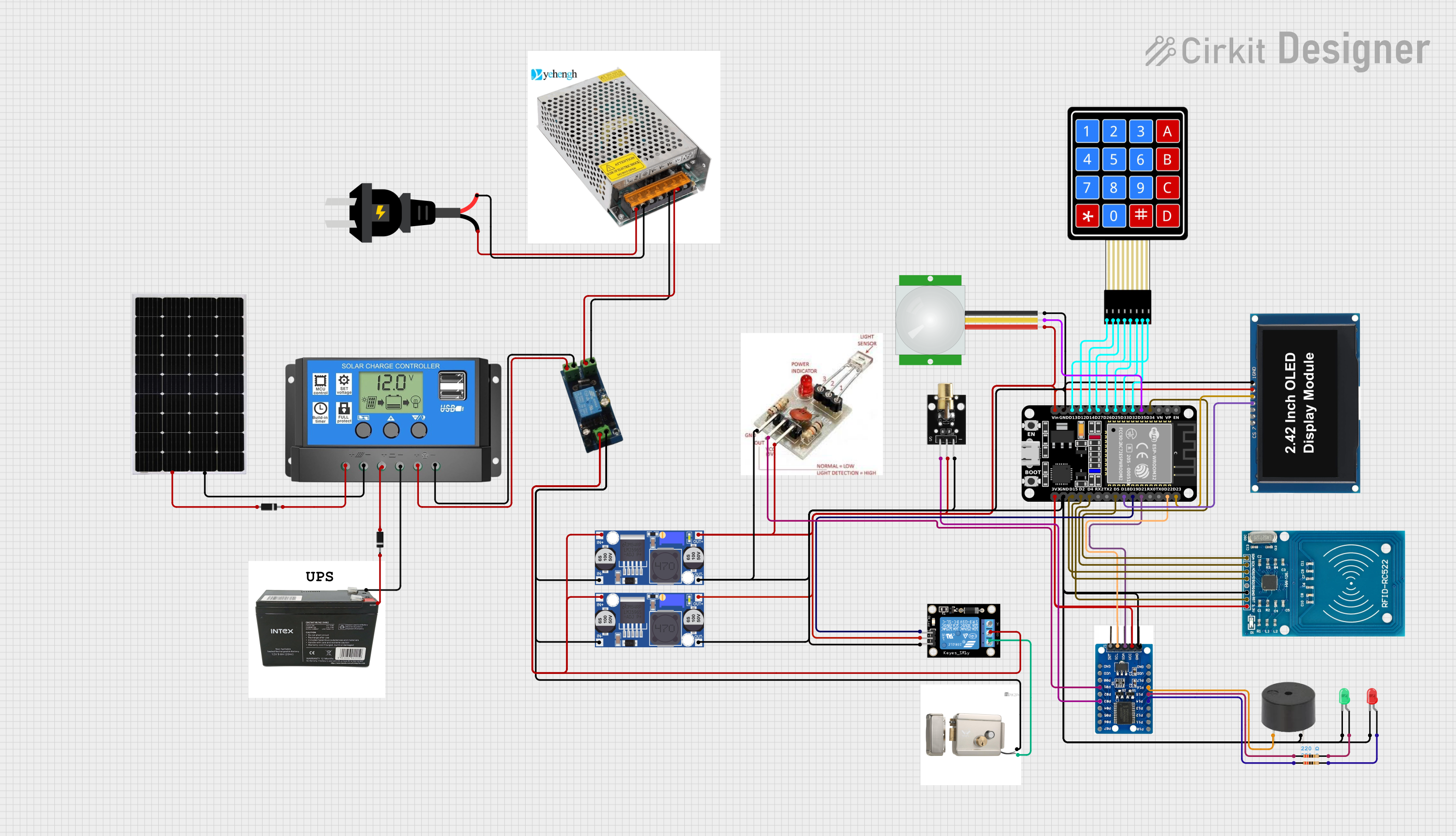
 Open Project in Cirkit Designer
Explore Projects Built with RELÉ DE SEGURANÇA

 Open Project in Cirkit Designer
 Open Project in Cirkit Designer
 Open Project in Cirkit Designer
 Open Project in Cirkit Designer
Common Applications and Use Cases
- Emergency stop (E-Stop) systems in industrial machinery
- Monitoring safety devices such as light curtains, safety mats, and interlock switches
- Ensuring safe operation of robotic systems
- Preventing unintended machine startup
- Fault detection in safety-critical circuits
Technical Specifications
Below are the general technical specifications for a typical safety relay. Always refer to the datasheet of the specific model for exact details.
Key Technical Details
- Operating Voltage: 24V DC or 230V AC (model-dependent)
- Contact Configuration: 2 to 4 safety contacts (NO) and 1 auxiliary contact (NC)
- Switching Capacity: Up to 6A at 230V AC
- Response Time: Typically < 20ms
- Operating Temperature: -25°C to +55°C
- Mounting: DIN rail
- Safety Standards Compliance: EN ISO 13849-1, IEC 62061, and EN 61508
Pin Configuration and Descriptions
The pin configuration of a safety relay may vary depending on the model. Below is a typical example:
| Pin Number | Label | Description |
|---|---|---|
| 1, 2 | A1, A2 | Coil terminals (power supply input) |
| 3, 4 | 13, 14 | Safety contact 1 (Normally Open - NO) |
| 5, 6 | 23, 24 | Safety contact 2 (Normally Open - NO) |
| 7, 8 | 31, 32 | Auxiliary contact (Normally Closed - NC) |
| 9, 10 | S11, S12 | Input for safety device (e.g., E-Stop button) |
| 11, 12 | S21, S22 | Input for safety device (e.g., light curtain) |
Usage Instructions
How to Use the Component in a Circuit
- Power Supply: Connect the appropriate voltage to the coil terminals (A1 and A2). Ensure the power supply matches the relay's operating voltage.
- Safety Device Inputs: Connect the safety devices (e.g., emergency stop button, light curtain) to the input terminals (e.g., S11-S12, S21-S22). Follow the wiring diagram provided in the relay's datasheet.
- Output Contacts: Wire the safety contacts (e.g., 13-14, 23-24) to the control circuit of the machinery. These contacts will open or close based on the safety relay's status.
- Auxiliary Contact: Use the auxiliary contact (31-32) for monitoring or signaling purposes, such as sending a status signal to a PLC.
- Testing: After wiring, test the system by activating the safety devices to ensure the relay responds correctly.
Important Considerations and Best Practices
- Always follow the wiring diagram and installation instructions provided by the manufacturer.
- Ensure the safety relay is compatible with the safety devices and machinery in your system.
- Regularly test the safety relay and associated devices to verify proper operation.
- Use proper fuses or circuit breakers to protect the relay and connected devices.
- Avoid exposing the relay to excessive vibration, moisture, or temperatures outside its operating range.
Example: Connecting a Safety Relay to an Arduino UNO
While safety relays are typically used in industrial systems, they can also be integrated with microcontrollers like the Arduino UNO for educational or prototyping purposes. Below is an example of how to monitor the status of a safety relay using an Arduino.
// Example: Monitoring a Safety Relay with Arduino UNO
// This code reads the status of the safety relay's auxiliary contact (NC)
// and turns on an LED if the relay is triggered (contact opens).

const int relayPin = 2;  // Pin connected to the relay's auxiliary contact
const int ledPin = 13;   // Pin connected to an LED

void setup() {
  pinMode(relayPin, INPUT_PULLUP); // Set relayPin as input with pull-up resistor
  pinMode(ledPin, OUTPUT);        // Set ledPin as output
}

void loop() {
  int relayStatus = digitalRead(relayPin); // Read the relay's status

  if (relayStatus == HIGH) {
    // Relay is triggered (auxiliary contact is open)
    digitalWrite(ledPin, HIGH); // Turn on the LED
  } else {
    // Relay is not triggered (auxiliary contact is closed)
    digitalWrite(ledPin, LOW);  // Turn off the LED
  }
}
Troubleshooting and FAQs
Common Issues and Solutions
Relay Does Not Activate
- Cause: Incorrect power supply voltage or wiring.
- Solution: Verify the power supply voltage and ensure proper wiring to the coil terminals.
Safety Devices Not Detected
- Cause: Faulty wiring or incompatible safety devices.
- Solution: Check the wiring and ensure the safety devices meet the relay's specifications.
Contacts Do Not Switch
- Cause: Damaged or worn-out contacts.
- Solution: Inspect the relay and replace it if necessary.
Intermittent Operation
- Cause: Loose connections or environmental factors (e.g., vibration).
- Solution: Secure all connections and ensure the relay is installed in a stable environment.
FAQs
Q: Can I use a safety relay with a standard relay in the same circuit?
A: Yes, but ensure the safety relay is used for safety-critical functions, while the standard relay handles non-safety-related tasks.
Q: How often should I test a safety relay?
A: It is recommended to test safety relays at least once a month or as specified by the manufacturer.
Q: Can a safety relay be reset automatically?
A: Some safety relays support automatic reset, but manual reset is preferred in most safety-critical applications to ensure proper inspection after a fault.
Q: What is the difference between a safety relay and a standard relay?
A: A safety relay is specifically designed to meet safety standards and includes features like fault detection and redundancy, whereas a standard relay does not.