How to Use 7A Dual SKU DRI004 motor driver: Examples, Pinouts, and Specs
DFRobot 7A Dual SKU DRI004 Motor Driver Documentation
1. Introduction
The DFRobot 7A Dual SKU DRI004 Motor Driver is a high-performance motor driver designed to control two DC motors simultaneously. With a maximum current capacity of 7A per channel, this motor driver is ideal for robotics, automation, and other applications requiring precise motor control. Its compact design and robust features make it suitable for hobbyists and professionals alike.
Common Applications:
- Robotics (e.g., mobile robots, robotic arms)
- Automated guided vehicles (AGVs)
- Conveyor belt systems
- Smart home devices (e.g., motorized curtains, doors)
- DIY projects involving DC motor control
This motor driver is compatible with microcontrollers like Arduino, Raspberry Pi, and other development boards, making it versatile and easy to integrate into various projects.
2. Technical Specifications
The following table outlines the key technical specifications of the DFRobot 7A Dual SKU DRI004 Motor Driver:
| Parameter | Specification |
|---|---|
| Operating Voltage | 6V - 27V |
| Maximum Current (per channel) | 7A |
| Control Logic Voltage | 3.3V - 5V |
| Number of Channels | 2 (dual motor control) |
| PWM Frequency | Up to 20 kHz |
| Dimensions | 60mm x 50mm x 15mm |
| Weight | 30g |
| Operating Temperature | -20°C to 85°C |
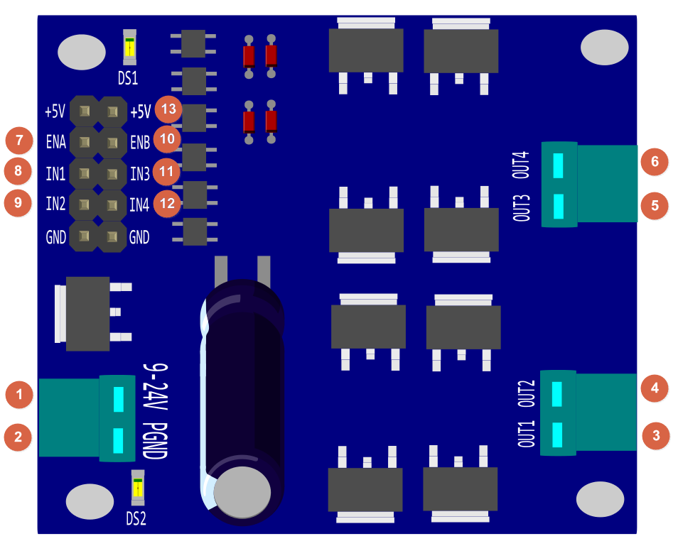
Pin Configuration and Descriptions
The motor driver has a simple pinout for easy integration. Below is the pin configuration:
| Pin Name | Type | Description |
|---|---|---|
| VIN | Power Input | Connect to the motor power supply (6V - 27V). |
| GND | Ground | Common ground for the motor driver and control system. |
| IN1 | Control Input | Input signal to control Motor 1 direction. |
| IN2 | Control Input | Input signal to control Motor 1 direction. |
| IN3 | Control Input | Input signal to control Motor 2 direction. |
| IN4 | Control Input | Input signal to control Motor 2 direction. |
| ENA | PWM Input | PWM signal to control the speed of Motor 1. |
| ENB | PWM Input | PWM signal to control the speed of Motor 2. |
| OUT1 | Motor Output | Connect to one terminal of Motor 1. |
| OUT2 | Motor Output | Connect to the other terminal of Motor 1. |
| OUT3 | Motor Output | Connect to one terminal of Motor 2. |
| OUT4 | Motor Output | Connect to the other terminal of Motor 2. |
3. Usage Instructions
Connecting the Motor Driver to an Arduino UNO
To use the DFRobot 7A Dual SKU DRI004 Motor Driver with an Arduino UNO, follow these steps:
Power Supply:
- Connect the VIN pin to a DC power source (6V - 27V) suitable for your motors.
- Connect the GND pin to the ground of the power source and the Arduino.
Motor Connections:
- Connect the terminals of Motor 1 to OUT1 and OUT2.
- Connect the terminals of Motor 2 to OUT3 and OUT4.
Control Pins:
- Connect IN1, IN2, IN3, and IN4 to digital pins on the Arduino.
- Connect ENA and ENB to PWM-capable pins on the Arduino for speed control.
Arduino Code:
- Use the following example code to control the motors.
Example Arduino Code
// Example code to control two DC motors using the DFRobot 7A Dual SKU DRI004 Motor Driver

// Define motor control pins
#define IN1 7  // Motor 1 direction control pin
#define IN2 6  // Motor 1 direction control pin
#define ENA 5  // Motor 1 speed control (PWM pin)
#define IN3 4  // Motor 2 direction control pin
#define IN4 3  // Motor 2 direction control pin
#define ENB 2  // Motor 2 speed control (PWM pin)

void setup() {
  // Set motor control pins as outputs
  pinMode(IN1, OUTPUT);
  pinMode(IN2, OUTPUT);
  pinMode(ENA, OUTPUT);
  pinMode(IN3, OUTPUT);
  pinMode(IN4, OUTPUT);
  pinMode(ENB, OUTPUT);
}

void loop() {
  // Motor 1: Forward at 50% speed
  digitalWrite(IN1, HIGH);
  digitalWrite(IN2, LOW);
  analogWrite(ENA, 128); // 50% duty cycle (0-255)

  // Motor 2: Reverse at 75% speed
  digitalWrite(IN3, LOW);
  digitalWrite(IN4, HIGH);
  analogWrite(ENB, 192); // 75% duty cycle (0-255)

  delay(2000); // Run motors for 2 seconds

  // Stop both motors
  digitalWrite(IN1, LOW);
  digitalWrite(IN2, LOW);
  digitalWrite(IN3, LOW);
  digitalWrite(IN4, LOW);
  analogWrite(ENA, 0);
  analogWrite(ENB, 0);

  delay(2000); // Wait for 2 seconds
}
Important Considerations:
- Ensure the motor power supply voltage matches the motor's operating voltage.
- Do not exceed the maximum current rating of 7A per channel.
- Use appropriate heat dissipation methods if operating at high currents for extended periods.
- Always connect the GND pin of the motor driver to the GND of the Arduino to ensure a common ground.
4. Troubleshooting and FAQs
Common Issues and Solutions
| Issue | Possible Cause | Solution |
|---|---|---|
| Motors not running | Incorrect wiring or loose connections | Double-check all connections and ensure proper wiring. |
| Motors running in the wrong direction | IN1/IN2 or IN3/IN4 signals are swapped | Reverse the connections of the control pins for the affected motor. |
| Motor speed not changing | PWM signal not properly configured | Ensure ENA and ENB are connected to PWM-capable pins on the Arduino. |
| Overheating of the motor driver | Exceeding current rating or poor ventilation | Reduce motor load or improve heat dissipation (e.g., add a heatsink). |
| Arduino resets when motors start | Power supply voltage drop | Use a separate power supply for the motors and the Arduino. |
Frequently Asked Questions (FAQs)
Can I use this motor driver with a 3.3V microcontroller?
- Yes, the control logic voltage range is 3.3V to 5V, making it compatible with 3.3V systems.
What type of motors can I use with this driver?
- This driver is designed for brushed DC motors with an operating voltage between 6V and 27V.
How do I control motor speed?
- Use a PWM signal on the ENA (Motor 1) and ENB (Motor 2) pins to control the speed.
Can I control only one motor with this driver?
- Yes, you can use only one channel if needed. Leave the unused channel unconnected.
This documentation provides a comprehensive guide to using the DFRobot 7A Dual SKU DRI004 Motor Driver. Whether you're a beginner or an experienced user, this motor driver is a reliable choice for your DC motor control needs.
Explore Projects Built with 7A Dual SKU DRI004 motor driver


Explore Projects Built with 7A Dual SKU DRI004 motor driver