Cirkit Designer
Your all-in-one circuit design IDE
Home /
Component Documentation
How to Use CT PZEM004T: Examples, Pinouts, and Specs

Introduction
The CT PZEM-004T is a versatile and widely-used electronic component designed for measuring electrical parameters such as voltage, current, power, and energy. It is particularly popular in applications involving energy monitoring, smart metering, and home automation systems. The PZEM-004T is often used in conjunction with microcontrollers like the Arduino UNO to provide real-time data on electrical consumption.
Explore Projects Built with CT PZEM004T
ESP32-Based Smart Environmental Monitoring System with Relay Control

This is a smart environmental monitoring and control system featuring an ESP32 microcontroller interfaced with a PZEM004T for power monitoring, relay modules for actuating bulbs and a fan, and an LCD for user interface. It includes flame, gas, and vibration sensors for safety monitoring purposes.
ESP32-Controlled AC Lighting System with Power Monitoring

This circuit features an ESP32 microcontroller interfaced with a PZEM004T power monitoring module and a 4-channel relay module controlling multiple AC LED bulbs. The ESP32 uses GPIO pins to control the relays, which in turn switch the LED bulbs on and off. The PZEM004T is connected to the ESP32 for communication and to a current sensor for monitoring power consumption of the connected load through the relay contacts.
ESP32-Based Smart Power Monitoring and Control System with Wi-Fi Connectivity

This circuit is a smart power monitoring and control system using an ESP32 microcontroller. It features multiple sensors and components, including PZEM-004T AC modules for voltage and current measurement, DS18B20 temperature sensors, an LCD for display, and solid-state relays for controlling power outlets. The system is integrated with Blynk for remote monitoring and control, and includes pushbuttons for local interaction.
ESP32 and PZEM004T-Based Smart Light Control with Current Sensing
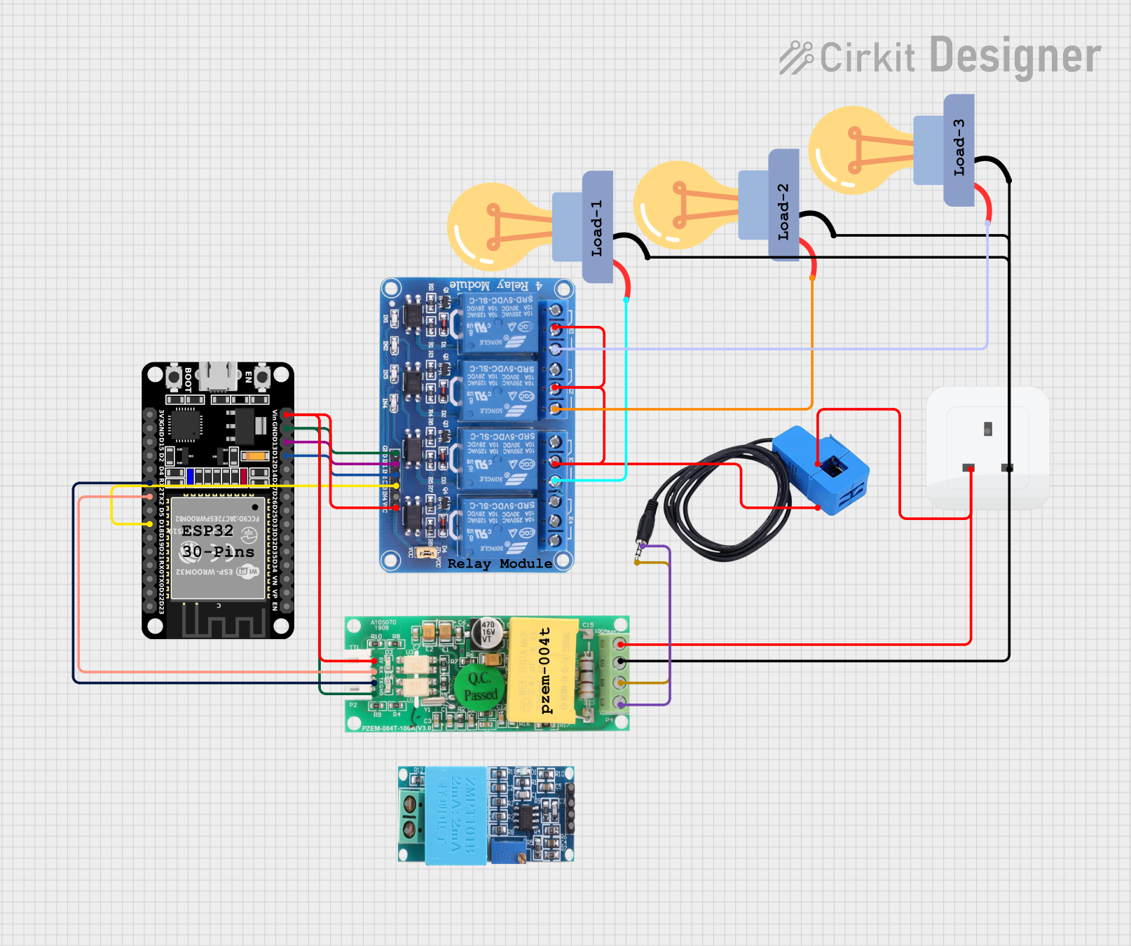
This circuit is designed for monitoring and controlling AC loads using an ESP32 microcontroller. It includes a PZEM004T module for measuring voltage, current, and power, and a 4-channel relay module to switch three LED bulbs. The ESP32 communicates with the PZEM004T via UART and controls the relays to manage the connected loads.
Explore Projects Built with CT PZEM004T
ESP32-Based Smart Environmental Monitoring System with Relay Control
This is a smart environmental monitoring and control system featuring an ESP32 microcontroller interfaced with a PZEM004T for power monitoring, relay modules for actuating bulbs and a fan, and an LCD for user interface. It includes flame, gas, and vibration sensors for safety monitoring purposes.
ESP32-Controlled AC Lighting System with Power Monitoring
This circuit features an ESP32 microcontroller interfaced with a PZEM004T power monitoring module and a 4-channel relay module controlling multiple AC LED bulbs. The ESP32 uses GPIO pins to control the relays, which in turn switch the LED bulbs on and off. The PZEM004T is connected to the ESP32 for communication and to a current sensor for monitoring power consumption of the connected load through the relay contacts.
ESP32-Based Smart Power Monitoring and Control System with Wi-Fi Connectivity
This circuit is a smart power monitoring and control system using an ESP32 microcontroller. It features multiple sensors and components, including PZEM-004T AC modules for voltage and current measurement, DS18B20 temperature sensors, an LCD for display, and solid-state relays for controlling power outlets. The system is integrated with Blynk for remote monitoring and control, and includes pushbuttons for local interaction.
ESP32 and PZEM004T-Based Smart Light Control with Current Sensing
This circuit is designed for monitoring and controlling AC loads using an ESP32 microcontroller. It includes a PZEM004T module for measuring voltage, current, and power, and a 4-channel relay module to switch three LED bulbs. The ESP32 communicates with the PZEM004T via UART and controls the relays to manage the connected loads.
Technical Specifications
Key Technical Details
| Parameter | Value |
|---|---|
| Voltage Range | 80-260V AC |
| Current Range | 0-100A (with external CT) |
| Power Range | 0-22kW |
| Energy Range | 0-9999kWh |
| Frequency Range | 45-65Hz |
| Communication | TTL Serial (3.3V/5V) |
| Accuracy | ±0.5% |
| Dimensions | 70mm x 40mm x 20mm |
Pin Configuration and Descriptions
| Pin Number | Pin Name | Description |
|---|---|---|
| 1 | VCC | Power supply (3.3V/5V) |
| 2 | GND | Ground |
| 3 | RX | Serial data receive |
| 4 | TX | Serial data transmit |
| 5 | A | Current transformer input (A) |
| 6 | B | Current transformer input (B) |
Usage Instructions
How to Use the Component in a Circuit
- Power Supply: Connect the VCC pin to a 3.3V or 5V power supply and the GND pin to the ground.
- Serial Communication: Connect the RX pin to the TX pin of the microcontroller and the TX pin to the RX pin of the microcontroller.
- Current Transformer: Connect the A and B pins to the current transformer (CT) to measure the current.
Important Considerations and Best Practices
- Ensure that the voltage and current ratings are within the specified range to avoid damage.
- Use proper isolation techniques when dealing with high voltage AC circuits.
- Calibrate the sensor for accurate measurements.
- Use appropriate pull-up or pull-down resistors if required by your microcontroller.
Example Code for Arduino UNO
#include <SoftwareSerial.h>

// Create a software serial object to communicate with PZEM-004T
SoftwareSerial pzem(10, 11); // RX, TX

void setup() {
  Serial.begin(9600); // Initialize serial communication with the computer
  pzem.begin(9600);   // Initialize serial communication with PZEM-004T
}

void loop() {
  // Request data from PZEM-004T
  pzem.write(0xB0); // Command to read voltage
  delay(100);       // Wait for the response

  if (pzem.available()) {
    // Read the response from PZEM-004T
    byte response[7];
    for (int i = 0; i < 7; i++) {
      response[i] = pzem.read();
    }

    // Calculate voltage from the response
    float voltage = (response[2] << 8 | response[3]) / 10.0;
    Serial.print("Voltage: ");
    Serial.print(voltage);
    Serial.println(" V");
  }

  delay(1000); // Wait for a second before the next reading
}
Troubleshooting and FAQs
Common Issues Users Might Face
- No Data Received: Ensure that the RX and TX pins are correctly connected and that the baud rate matches.
- Inaccurate Readings: Calibrate the sensor and ensure that the current transformer is properly connected.
- Power Supply Issues: Verify that the VCC and GND pins are correctly connected to a stable power source.
Solutions and Tips for Troubleshooting
- Check Connections: Double-check all connections, especially the RX and TX pins.
- Verify Power Supply: Ensure that the power supply voltage is within the specified range.
- Use Serial Monitor: Use the Arduino Serial Monitor to debug and verify the data received from the PZEM-004T.
- Consult Datasheet: Refer to the PZEM-004T datasheet for detailed information and troubleshooting tips.
By following this documentation, users can effectively integrate the CT PZEM-004T into their projects, ensuring accurate and reliable measurements of electrical parameters.