How to Use PIC16F84A: Examples, Pinouts, and Specs
Introduction
The PIC16F84A is an 8-bit microcontroller developed by Microchip Technology. It features 1K words of program memory, 64 bytes of RAM, and 13 I/O pins, making it a versatile and reliable choice for a wide range of embedded system applications. Its simplicity, ease of programming, and robust design have made it a popular choice among hobbyists and professionals alike.
Explore Projects Built with PIC16F84A

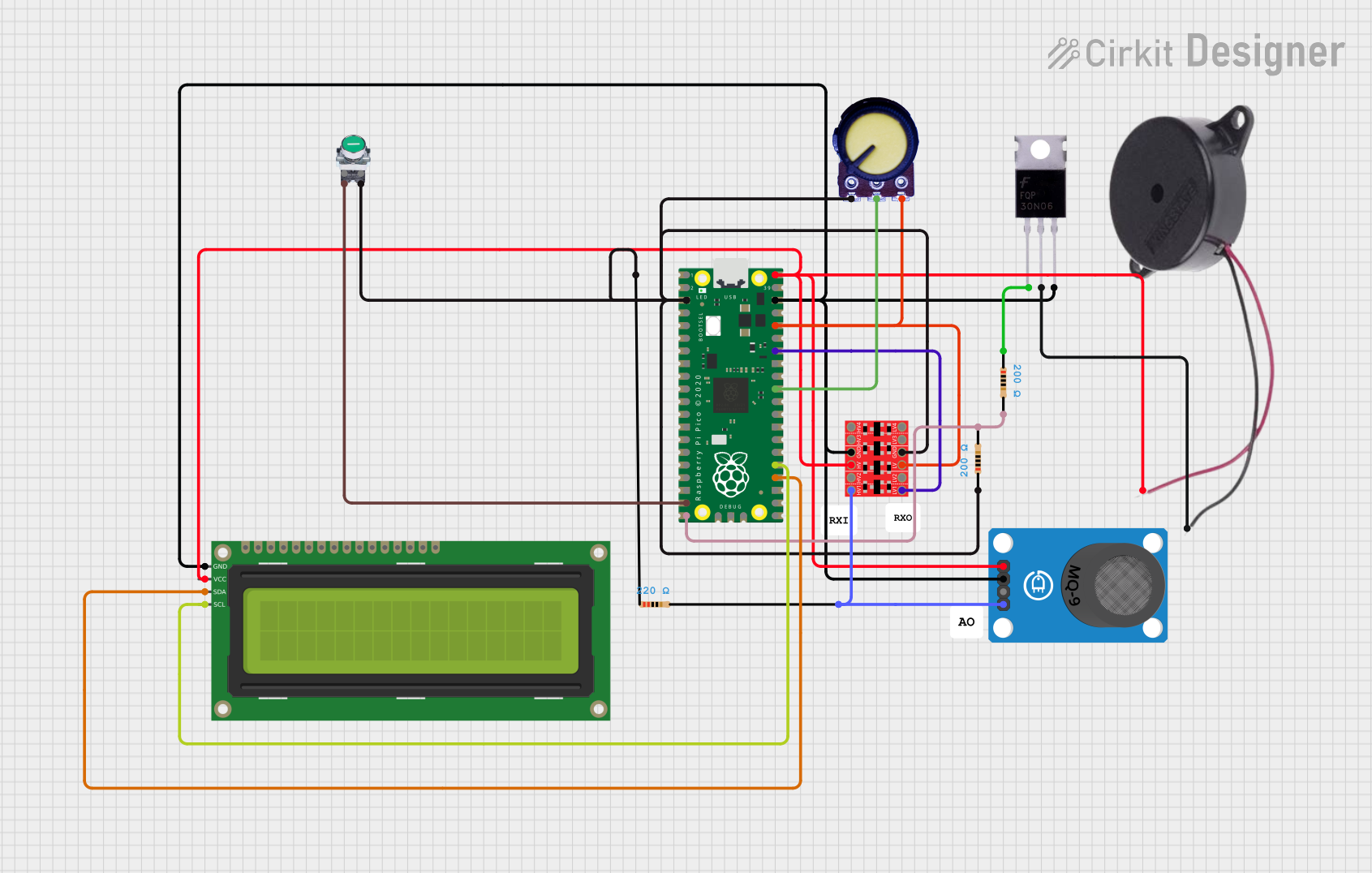

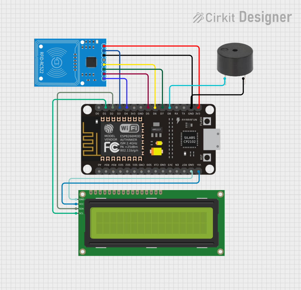
Explore Projects Built with PIC16F84A
Common Applications and Use Cases
- Home automation systems
- Industrial control systems
- Robotics and motor control
- Sensor interfacing and data acquisition
- Educational projects and prototyping
Technical Specifications
The following table outlines the key technical details of the PIC16F84A microcontroller:
| Parameter | Value |
|---|---|
| Program Memory | 1K words |
| Data Memory (RAM) | 64 bytes |
| EEPROM | 64 bytes |
| Operating Voltage Range | 2.0V to 5.5V |
| Clock Speed | Up to 20 MHz |
| I/O Pins | 13 |
| Timers | 1 (8-bit) |
| Interrupts | 4 |
| Instruction Set | 35 instructions (RISC) |
| Package Types | PDIP, SOIC, SSOP, TQFP |
Pin Configuration and Descriptions
The PIC16F84A has an 18-pin configuration. The table below describes each pin:
| Pin Number | Pin Name | Description |
|---|---|---|
| 1 | RA2/AN2 | Digital I/O or Analog Input |
| 2 | RA3/AN3 | Digital I/O or Analog Input |
| 3 | RA4/T0CKI | Digital I/O or Timer0 Clock Input |
| 4 | MCLR/VPP | Master Clear (Reset) / Programming Voltage Input |
| 5 | VSS | Ground |
| 6 | RB0/INT | Digital I/O or External Interrupt Input |
| 7 | RB1 | Digital I/O |
| 8 | RB2 | Digital I/O |
| 9 | RB3 | Digital I/O |
| 10 | RB4 | Digital I/O |
| 11 | RB5 | Digital I/O |
| 12 | RB6/PGC | Digital I/O or Programming Clock Input |
| 13 | RB7/PGD | Digital I/O or Programming Data Input/Output |
| 14 | VDD | Positive Supply Voltage |
| 15 | OSC1/CLKIN | Oscillator Input / External Clock Input |
| 16 | OSC2/CLKOUT | Oscillator Output / Clock Output |
| 17 | RA0/AN0 | Digital I/O or Analog Input |
| 18 | RA1/AN1 | Digital I/O or Analog Input |
Usage Instructions
How to Use the PIC16F84A in a Circuit
- Power Supply: Connect the VDD pin to a 5V power source and the VSS pin to ground.
- Oscillator Setup: Connect an external crystal oscillator (e.g., 4 MHz) between the OSC1 and OSC2 pins. Add two capacitors (typically 22pF) to stabilize the oscillator.
- Reset Pin: Connect the MCLR pin to 5V through a 10kΩ pull-up resistor. Optionally, add a push-button switch to ground for manual reset functionality.
- I/O Pins: Configure the I/O pins (RA0-RA4, RB0-RB7) as input or output in the program code.
- Programming: Use an ICSP (In-Circuit Serial Programming) tool to upload code to the microcontroller via the RB6 (PGC) and RB7 (PGD) pins.
Important Considerations and Best Practices
- Ensure the power supply voltage is within the specified range (2.0V to 5.5V).
- Use decoupling capacitors (e.g., 0.1µF) near the VDD and VSS pins to reduce noise.
- Avoid leaving unused pins floating; connect them to ground or configure them as outputs.
- Use proper pull-up or pull-down resistors for input pins to prevent erratic behavior.
Example Code for Arduino UNO Integration
Although the PIC16F84A is not directly programmable via Arduino IDE, it can communicate with an Arduino UNO. Below is an example of interfacing the PIC16F84A with an Arduino UNO to toggle an LED connected to the PIC microcontroller:
// Arduino UNO code to send a signal to the PIC16F84A
// This code toggles a digital pin connected to the PIC16F84A

#define PIC_PIN 7  // Arduino pin connected to the PIC16F84A input pin

void setup() {
  pinMode(PIC_PIN, OUTPUT);  // Set the pin as output
}

void loop() {
  digitalWrite(PIC_PIN, HIGH);  // Send HIGH signal to the PIC
  delay(1000);                  // Wait for 1 second
  digitalWrite(PIC_PIN, LOW);   // Send LOW signal to the PIC
  delay(1000);                  // Wait for 1 second
}
Troubleshooting and FAQs
Common Issues and Solutions
Microcontroller Not Responding
- Cause: Incorrect power supply or oscillator configuration.
- Solution: Verify the power supply voltage and ensure the crystal oscillator and capacitors are correctly connected.
Program Not Uploading
- Cause: Faulty ICSP connection or incorrect programming voltage.
- Solution: Check the connections to the RB6 (PGC) and RB7 (PGD) pins. Ensure the MCLR pin is receiving the correct programming voltage.
Erratic Behavior of I/O Pins
- Cause: Floating input pins or insufficient pull-up/pull-down resistors.
- Solution: Add appropriate pull-up or pull-down resistors to input pins.
Overheating
- Cause: Excessive current draw or incorrect wiring.
- Solution: Check the circuit for short circuits and ensure the current draw is within the microcontroller's limits.
FAQs
Q: Can the PIC16F84A be programmed using Arduino IDE?
A: No, the PIC16F84A requires a dedicated programmer and software such as MPLAB IDE or a third-party PIC programmer.
Q: What is the maximum clock speed of the PIC16F84A?
A: The maximum clock speed is 20 MHz.
Q: Can I use the PIC16F84A for analog-to-digital conversion?
A: No, the PIC16F84A does not have a built-in ADC module. You would need an external ADC for such functionality.
Q: How do I protect the microcontroller from voltage spikes?
A: Use decoupling capacitors near the power pins and consider adding a TVS diode for additional protection.