How to Use Flex Sensor: Examples, Pinouts, and Specs
Introduction
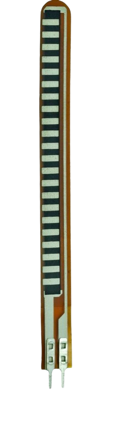
The Flex Sensor (Manufacturer: Spectra Symbol, Part ID: 1070) is a variable resistor that alters its resistance based on the degree of bending or flexing. This unique property makes it an essential component in applications requiring motion or position detection. The sensor is widely used in fields such as robotics, wearable technology, gaming peripherals, and interactive devices. Its ability to provide real-time feedback on bending makes it ideal for creating innovative and responsive systems.
Explore Projects Built with Flex Sensor
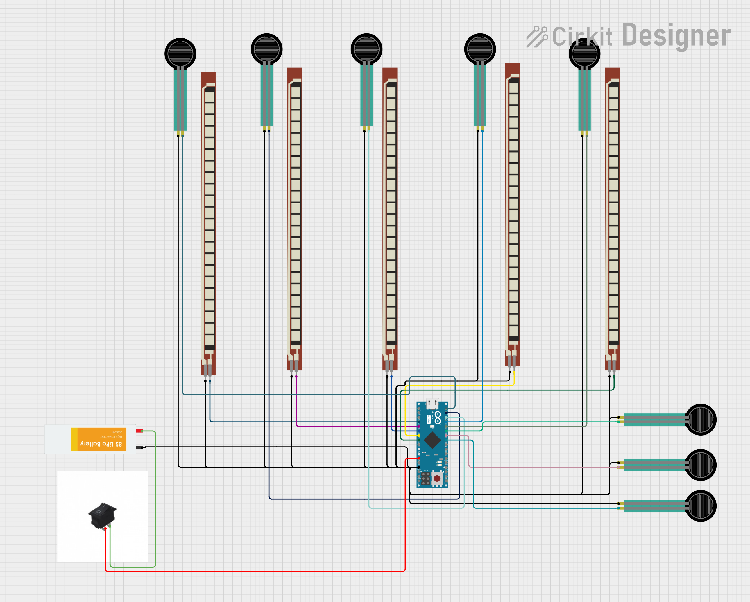
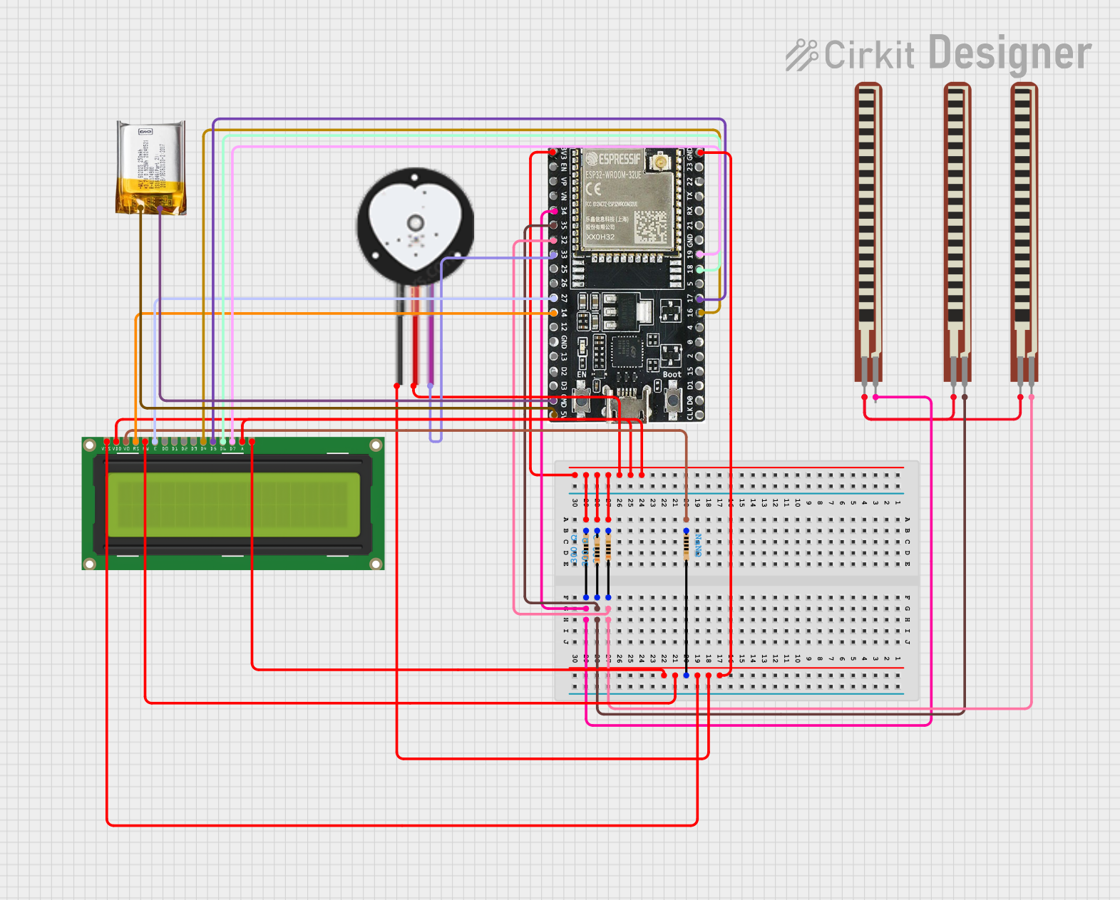
Explore Projects Built with Flex Sensor
Common Applications:
- Robotics: Detecting joint movement or angular displacement.
- Wearable Technology: Measuring finger or limb flexion in gloves or exoskeletons.
- Gaming and VR: Capturing hand gestures for immersive experiences.
- Medical Devices: Monitoring body posture or joint movement in rehabilitation systems.
- Interactive Devices: Enabling touchless control or gesture-based interfaces.
Technical Specifications
Key Technical Details:
- Manufacturer: Spectra Symbol
- Part ID: 1070
- Resistance (Flat State): 10 kΩ (±30%)
- Resistance (Bent State): Up to 40 kΩ (depending on the degree of bending)
- Bend Angle Range: 0° (flat) to ~90° (maximum bend)
- Power Rating: 0.5 W (maximum)
- Operating Voltage: 0–5 V
- Temperature Range: -35°C to +80°C
- Lifespan: Over 1 million flex cycles
- Dimensions: 4.5 inches (length) x 0.25 inches (width)
Pin Configuration and Descriptions:
The Flex Sensor has two pins, as shown in the table below:
| Pin | Name | Description |
|---|---|---|
| 1 | Signal/Output | Outputs a variable resistance based on the degree of bending. |
| 2 | Ground (GND) | Connects to the ground of the circuit. |
Usage Instructions
How to Use the Flex Sensor in a Circuit:
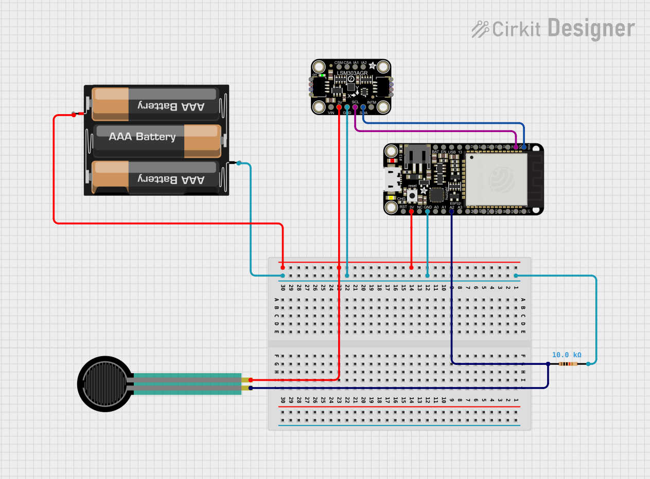
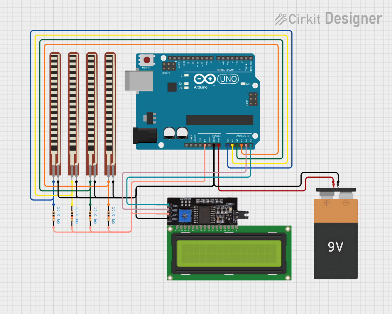
Connect the Sensor:
- Attach one pin of the Flex Sensor to a fixed voltage (e.g., 5V).
- Connect the other pin to a pull-down resistor (e.g., 10 kΩ) and then to ground.
- The junction between the Flex Sensor and the pull-down resistor serves as the output signal.
Read the Output:
- The output voltage varies with the sensor's resistance. Use an analog-to-digital converter (ADC) to measure this voltage.
- For example, connect the output to an analog input pin of a microcontroller (e.g., Arduino UNO).
Calibrate the Sensor:
- Measure the output voltage in both flat and fully bent states.
- Map the voltage range to the desired application (e.g., angle or position).
Important Considerations and Best Practices:
- Avoid Overbending: Do not exceed the recommended bend angle (~90°) to prevent damage.
- Secure Mounting: Ensure the sensor is securely mounted to avoid inaccurate readings due to movement.
- Debounce the Signal: Use software filtering to smooth out noise in the output signal.
- Temperature Effects: Be aware that extreme temperatures may slightly affect resistance values.
Example: Using the Flex Sensor with Arduino UNO
Below is an example code to read the Flex Sensor's output and display the results in the Serial Monitor:
// Flex Sensor Example with Arduino UNO
// Reads the sensor value and maps it to a bend angle (0° to 90°)

const int flexPin = A0; // Analog pin connected to the Flex Sensor
int sensorValue = 0;   // Variable to store the raw sensor reading
int angle = 0;         // Variable to store the calculated bend angle

void setup() {
  Serial.begin(9600); // Initialize serial communication at 9600 baud
}

void loop() {
  sensorValue = analogRead(flexPin); // Read the raw sensor value
  // Map the sensor value (0-1023) to an approximate angle (0°-90°)
  angle = map(sensorValue, 512, 1023, 0, 90);
  // Adjust the mapping range based on calibration for your specific sensor

  // Print the raw value and calculated angle to the Serial Monitor
  Serial.print("Sensor Value: ");
  Serial.print(sensorValue);
  Serial.print(" | Bend Angle: ");
  Serial.print(angle);
  Serial.println("°");

  delay(100); // Delay for stability
}
Troubleshooting and FAQs
Common Issues and Solutions:
Inconsistent Readings:
- Cause: Loose connections or unstable mounting.
- Solution: Ensure the sensor is securely mounted and all connections are tight.
No Output Signal:
- Cause: Incorrect wiring or damaged sensor.
- Solution: Double-check the wiring and test the sensor with a multimeter.
Output Signal Too Noisy:
- Cause: Electrical noise or interference.
- Solution: Add a capacitor (e.g., 0.1 µF) across the sensor's output and ground to filter noise.
Sensor Not Responding to Bending:
- Cause: Overbending or physical damage.
- Solution: Inspect the sensor for visible damage and replace if necessary.
FAQs:
Q: Can the Flex Sensor detect bending in both directions?
A: Yes, but the resistance change is typically calibrated for one direction. For bidirectional bending, use two sensors.Q: How do I extend the lifespan of the Flex Sensor?
A: Avoid overbending, operate within the specified temperature range, and handle the sensor carefully during installation.Q: Can I use the Flex Sensor with a 3.3V system?
A: Yes, the sensor works with lower voltages, but the output range will be reduced. Adjust your circuit and code accordingly.Q: How do I calibrate the sensor for precise measurements?
A: Measure the output voltage at known bend angles (e.g., 0° and 90°) and use these values to map the sensor's response.
This documentation provides a comprehensive guide to understanding, using, and troubleshooting the Spectra Symbol Flex Sensor (Part ID: 1070). With proper handling and integration, this versatile component can enhance a wide range of projects and applications.